 Here's
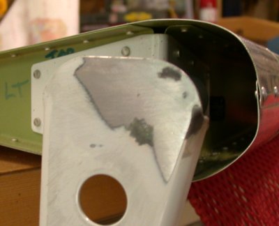
the welded-over hole, all ground & filed down smooth.
Here's
the welded-over hole, all ground & filed down smooth.EMPENNAGE MOUNTING AND RIGGING - AUGUST, 2003
Aug 5 - I'm back from a great week at AirVenture, Oshkosh. It was lots of fun, and I learned a lot. I spent most of each day in the workshops. I spent 2 whole days with Kent White on metalworking. I did a composites class, and I spent another whole day at a workshop on building a Superior 360 engine. I am still agonizing over engine choices, and still thoroughly confused by avionics choices. See my engine page for the latest updates there. While at OSH, I bought my control stick grips and an engine pre-oiler from Infinity Aerospace, and the AOA Professional angle of attack indicator system from Proprietary Software Systems.
Back at home, I finished grinding and filing the welds flat and smooth on my elevator horns. I bought some temporary hinge mounting pins from Avery at the show, but Avery made them a tad too long, so I modified those. I also threaded some of the ones I had already made, to use with Avery's screw-on handle. Cut out the H-stab skins so the elevators would swing free. I hung the elevators again and readjusted the Heim joints in one turn for a closer fit. I found that the left elevator was pretty well balanced before any paint or adding the electric trim motor, so once I added the motor, the weight is too light. I emailed Van's about that. I also trimmed the RT elevator weight some, around the leading edge. I got out my tip fiberglass and studied how that was going to go together with the elevators and counterweights. Noticed the rudder T/E was a bit rough, so I smoothed that with a file.
I redrilled the LT elevator bearing hole. It seems to be perfect this time. I used only a 1/4" drill bit (no starter bits), and used the bearing as a guide, being careful to keep the bit perfectly straight and not spin the bit in the bearing, and not spin the bearing too fast.
Then, I removed the LT elevator and worked on the electric trim servo and access cover. The cover was bowed up around the edges from the dimpling, so I straightened that out, so it would lay flatter. I also ground off the sides of the nutplates, where they protruded into the opening for the motor. I also trimmed a bit of the opening, to make it far easier to get the motor and cover in and out. I was going to hook it up, but I need to get some wire first, to lengthen the minimal leads that came with the servo. I mounted the motor to the cover. NOTE - be very careful with the little screws that mount the motor. My electric screwdriver snapped one easily. It seems like I worked a lot of hours, but didn't really accomplish a whole lot today. I did spend some more time finalizing the Superior Engine Buildup page and looking through the Van's accessories catalog. I've got about 20 hours into making the engine buildup page. 11.5 hr + 1.0 doc
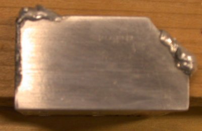
Here's
the welded-over hole, all ground & filed down smooth.
![]() Cut the H-stab skins for clearance for the elevator counterweight arms to
swing by. I don't know why they didn't come with this clearance
already cut; so I could get it closer myself, I guess.
Cut the H-stab skins for clearance for the elevator counterweight arms to
swing by. I don't know why they didn't come with this clearance
already cut; so I could get it closer myself, I guess.
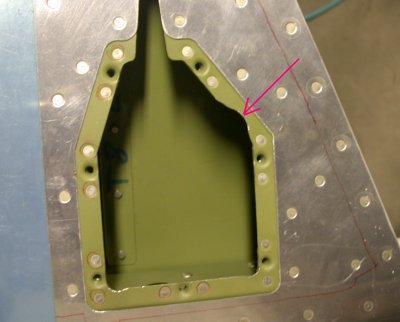 I used a carbide rotary cutter to trim the inner edges of the nutplates,
where they protruded into the opening. I also enlarged the opening at
the arrow. It makes it MUCH easier to get that motor in and out of
there. I'd started doing this when I was at Alexander Technical
Center, building the tail, but their rotary cutter was junk, and wouldn't
cut the nutplates. My rotary cutter did it easily.
I used a carbide rotary cutter to trim the inner edges of the nutplates,
where they protruded into the opening. I also enlarged the opening at
the arrow. It makes it MUCH easier to get that motor in and out of
there. I'd started doing this when I was at Alexander Technical
Center, building the tail, but their rotary cutter was junk, and wouldn't
cut the nutplates. My rotary cutter did it easily.
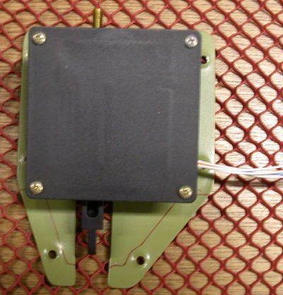 Here's the trim servo, mounted to the cover. Those little screws snap
very easily, which is why one is now silver and the rest are gold.
Here's the trim servo, mounted to the cover. Those little screws snap
very easily, which is why one is now silver and the rest are gold.
Aug 6 - I talked to Van's about some questions I had concerning the wing tips and light options. I had thought someone had told me I had the new "sheared wing tips", but they sure don't look "sheared" to me. Apparently the (older) ones that I would call "sheared" are the non-sheared. Gus told me ALL RV-7s have sheared wing tips. These are the ones with the rounded ends and the nav lights in the fwd L/E corner. So anyway, the bottom line is that no white light can be seen from where the nav lights go on the "sheared" style, so I do need to put my rear white light in the aft base of the rudder.
I returned to working on the plane, filing and grinding the weld on the inside of the elevator horns. Yesterday, I ordered an air-powered file from MSC, to help with this. Grinding and filing the outside of the horns was much easier than doing it on the inside surface. I also began rigging the electric elevator trim motor. I had to hook up a battery and make sure the motor and display were in the center of their travel, while the trim tab was in its neutral position. Then I cut the actuating rod to length.
I drilled the elevator horns again for the bearing bolt hole. They came out perfect this time. I didn't bother with a starter bit - I just carefully positioned a 1/4" drill bit in the bearing and made very sure it was straight and not binding in the bearing, then drilled out the horn. I did it for both sides, and a bolt now will go from the bearing right through the elevator horn like it's all one hole. I deburred the horn holes and reprimed the horns. I also spent an incredible 1.5 hours online ordering some accessories from Van's. I sent them an email about how horribly slow it was to use their web store. I neatly trimmed up the RT elevator counterweight, so the profile of the lead matched the profile of the sheet metal, where they are exposed.
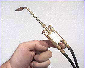
If you read my "Empennage Build" page, you may recall that I was very unhappy that Jacob at Alexander Technical Center pounded my LT elevator weight in so hard we couldn't get it back out. After I got the RT elevator counterweight trimmed up nicely, I decided to work on the LT one. For starters, it is too light. It was barely OK before adding the trim servo, but now it is too light. I asked Van's for their advice, and they said any secure way I add more lead to it is OK. Another goodie I bought at OSH was a nice little micro oxy-acetylene torch from Kent White at TM Technologies, so I decided to use that and "weld" more lead onto the existing block. I used a wooden block, and was able to pound the weight out of the elevator arm. Then I trimmed it properly for a good snug fit. Then I dimpled the mount holes in the elevator arm, and machined out a groove in the lead to clear the dimples. With the lead weight out and trimmed, I used the new torch to "weld" some lead from wheel weights onto the back side of my existing counterweight. At first, it was easy, because I was doing it on the back side of the weight, where it is concave. After I filled up the concave part, it got a bit more difficult, with molten lead wanting to run off the side. So, the way it is right now, it's about right, but it will probably need just a bit more lead added to counter the weight of paint, assuming I paint the plane. 10.5 hr
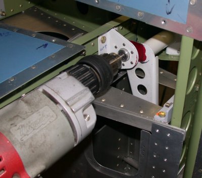
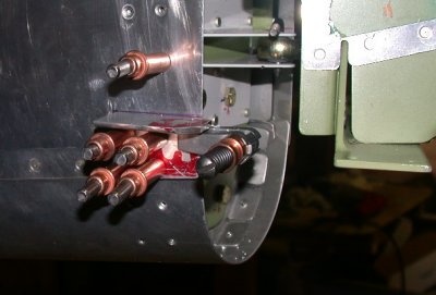
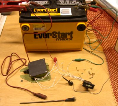 Here's the setup for driving the trim servo back and forth, to get it in the
center of its travel, so I could set the rod length. As the rod comes
with the kit, it is way too long. I also hooked up the indicator, to
make sure it works, and to ensure it indicates "center" when the
servo is centered. Unfortunately, the indicator has an EVEN number of
lights, so there is no center light. It's in the centered position in
this picture. So, I guess I will have to make a red dot or something
on the indicator after I install it, so I know where "centered"
is.
Here's the setup for driving the trim servo back and forth, to get it in the
center of its travel, so I could set the rod length. As the rod comes
with the kit, it is way too long. I also hooked up the indicator, to
make sure it works, and to ensure it indicates "center" when the
servo is centered. Unfortunately, the indicator has an EVEN number of
lights, so there is no center light. It's in the centered position in
this picture. So, I guess I will have to make a red dot or something
on the indicator after I install it, so I know where "centered"
is.
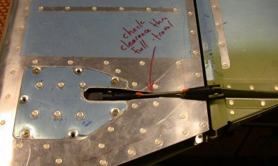 The elevator trim servo and rod installed. The electric leads that come with
the servo are too short to extend out of the elevator, so right now I can't check full
travel clearance with the elevator. I have ordered the Van's basic
wiring kit, so when that comes, I will lengthen the wires and make sure the
actuating arm & rod don't hit anything. It's a good idea to write
yourself reminders like this right on the plane, so you, as Roger's Rangers
said, "Don't forget nothing".
The elevator trim servo and rod installed. The electric leads that come with
the servo are too short to extend out of the elevator, so right now I can't check full
travel clearance with the elevator. I have ordered the Van's basic
wiring kit, so when that comes, I will lengthen the wires and make sure the
actuating arm & rod don't hit anything. It's a good idea to write
yourself reminders like this right on the plane, so you, as Roger's Rangers
said, "Don't forget nothing".
 Drilling out the elevator horns again, using the bearing as a drill guide
this time. They came out perfectly. Be sure the drill is in line
with the bearing when you do this. Check bit alignment by stopping periodically
and making sure the bit will slide easily in and out of the bearing, without
binding. Keep the drill RPMs down, so you don't overspeed the bearing.
Drilling out the elevator horns again, using the bearing as a drill guide
this time. They came out perfectly. Be sure the drill is in line
with the bearing when you do this. Check bit alignment by stopping periodically
and making sure the bit will slide easily in and out of the bearing, without
binding. Keep the drill RPMs down, so you don't overspeed the bearing.
 Here's a redrilled elevator horn, ready for repriming.
 Here
is a horn, reprimed. I put on many coats of primer, because the
original powder coating was so thick.
Here
is a horn, reprimed. I put on many coats of primer, because the
original powder coating was so thick.
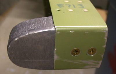 I trimmed the RT elevator counterweight so the fwd surfaces matched the
counterweight arm. Note the countersunk screw head holes. I'll
hit this with some primer next.
I trimmed the RT elevator counterweight so the fwd surfaces matched the
counterweight arm. Note the countersunk screw head holes. I'll
hit this with some primer next.
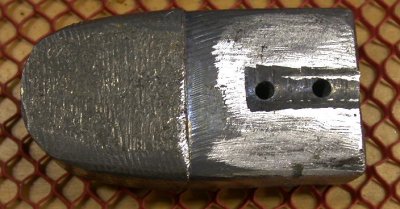 Here's the LT elevator counterweight, trimmed properly and using the proper
dimple clearance, rather than the hack job I had to do on the RT one at
Alexander Technical Center.
Here's the LT elevator counterweight, trimmed properly and using the proper
dimple clearance, rather than the hack job I had to do on the RT one at
Alexander Technical Center.
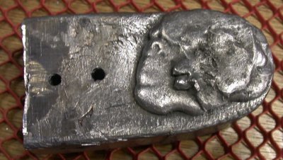 Yes, you CAN weld lead so it flows together well and creates one mass.
As you can see, though, I filled up the concave part, so I will have to make
a simple dam to hold the molten lead in place to add a bit more.
Yes, you CAN weld lead so it flows together well and creates one mass.
As you can see, though, I filled up the concave part, so I will have to make
a simple dam to hold the molten lead in place to add a bit more.
Aug 9 - Used modeling clay to make a dam around the LT elevator counterweight, and added a few more ounces of lead to the counterweight. Installed LT counterweight. Spent an inordinate amount of time searching for one of the screws for the LT counterweight. Cleaned up workbench. Fabricated and fitted LT F-792 Rudder Stop. Rather than make all the measured cuts on the stop, as per the plan, I cut out the basic rectangular shape, located the 4 holes, then scribed it to the fuselage skin panels, for a better fit. 9.0 hr
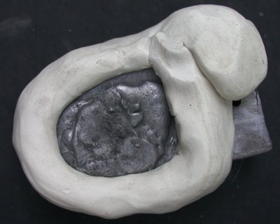 I
packed some modeling clay around the LT counterweight, so the molten lead
wouldn't run off the side or into the area where the counterweight fits into
the elevator arm.
I
packed some modeling clay around the LT counterweight, so the molten lead
wouldn't run off the side or into the area where the counterweight fits into
the elevator arm.
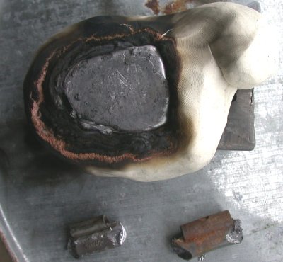 Hmmmm - I don't think this clay was designed for these temperatures. I
had to stop a couple times and blow out the flames. Once I had all
the lead melted in (from old wheel weights) that I wanted, I put plenty of
heat right in the center of the molten lead, to make the center molten spot
as deep into the counterweight as possible. This was more of a casting
job than a welding job.
Hmmmm - I don't think this clay was designed for these temperatures. I
had to stop a couple times and blow out the flames. Once I had all
the lead melted in (from old wheel weights) that I wanted, I put plenty of
heat right in the center of the molten lead, to make the center molten spot
as deep into the counterweight as possible. This was more of a casting
job than a welding job.
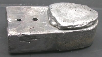 LT
counterweight all done - it came out well.
LT
counterweight all done - it came out well.
 LT
rudder stop clamped into place, and beginning the slow, tedious process of
gradually grinding (on my Scotch-Brite wheel) the rudder horn contact area
back until I had just the right rudder-to-elevator clearance. In
hindsight, maybe I should have just left it clamped here, and used a file to
cut it in-place until the clearance was right, instead of all the
clamp/measure/mark/remove/grind/reinstall iterations I went through.
LT
rudder stop clamped into place, and beginning the slow, tedious process of
gradually grinding (on my Scotch-Brite wheel) the rudder horn contact area
back until I had just the right rudder-to-elevator clearance. In
hindsight, maybe I should have just left it clamped here, and used a file to
cut it in-place until the clearance was right, instead of all the
clamp/measure/mark/remove/grind/reinstall iterations I went through.
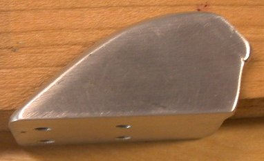
 Here's the
LT rudder stop, finished after setting the rudder travel, scribing,
cutting, and beveling the edges to match the bottom and rear of the skin it mounts
to, and smoothing the corners and transitions.
Here's the
LT rudder stop, finished after setting the rudder travel, scribing,
cutting, and beveling the edges to match the bottom and rear of the skin it mounts
to, and smoothing the corners and transitions.
Aug 10 - Fabricated and fitted RT rudder stop. Even though I made the initial cut for the edge that contacts the rudder horn leaving at least 1/8" more aluminum than specified in the plans, it still came up with a rudder-elevator clearance of 7/8", when it needs to be 1 1/8". So, I had to weld more aluminum to the stop surface. Spent a huge amount of time getting the rudder stops made to my satisfaction. 4.0 hr
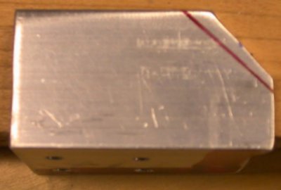 The
red line is where the cut should have been made, according to the
plan. As you can see, I made the first cut well away from that
line. I based this cut on where I ended up on the LT stop after
starting there with no cut and slowly grinding my way back until I had the proper
rudder-to-elevator clearance. But when I fitted this RT stop, as you
see it here, to the plane, I had only 7/8" clearance from the rudder
skin to the aft corner of the elevator, when I needed 1 1/8". NOTE
- when you make the cut for the edge that contacts the rudder horn, don't
follow the cut in the plan; leave LOTS of material, then slowly work your
way back to the proper rudder-to-elevator clearance. And keep in mind
that, as you cut it back and the rudder swings out more & more, that the
contact ANGLE will change slightly.
The
red line is where the cut should have been made, according to the
plan. As you can see, I made the first cut well away from that
line. I based this cut on where I ended up on the LT stop after
starting there with no cut and slowly grinding my way back until I had the proper
rudder-to-elevator clearance. But when I fitted this RT stop, as you
see it here, to the plane, I had only 7/8" clearance from the rudder
skin to the aft corner of the elevator, when I needed 1 1/8". NOTE
- when you make the cut for the edge that contacts the rudder horn, don't
follow the cut in the plan; leave LOTS of material, then slowly work your
way back to the proper rudder-to-elevator clearance. And keep in mind
that, as you cut it back and the rudder swings out more & more, that the
contact ANGLE will change slightly.
 I have a
MIG welder set up for aluminum, so I welded some more material onto the stop
where
the rudder horn hits it. The bead in the upper LT corner was
just a practice bead, to make sure I had the welder heat set right, and to
warm up this part before welding the contact area.
I have a
MIG welder set up for aluminum, so I welded some more material onto the stop
where
the rudder horn hits it. The bead in the upper LT corner was
just a practice bead, to make sure I had the welder heat set right, and to
warm up this part before welding the contact area.
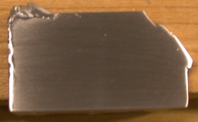 RT
stop, ground back to one nice smooth surface.
RT
stop, ground back to one nice smooth surface.
 And here is the RT stop, finished.
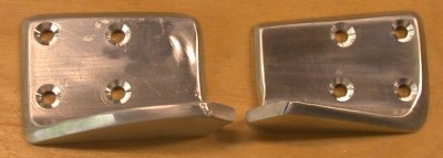
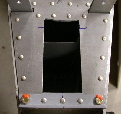
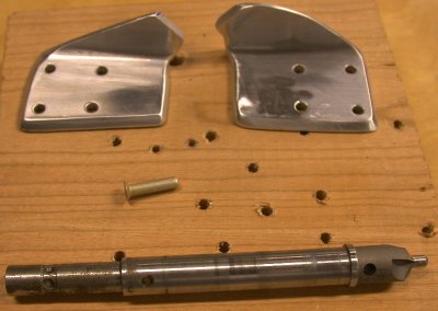 LT and RT elevator stops completed, except for countersinking. There
is no way to get a regular countersink stop in here for these rivet holes,
so I put the countersink on a drive shaft made from a dismantled countersink
microstop cage, and I will use this setup on my drill press. As you
can see, I did not make the LT and RT stops symmetrical. On the RT one,
I left extra material in the leg with no mounting holes. This is
so I can drill a hole in the center of it to use as an attach point for a
ground rudder lock.
LT and RT elevator stops completed, except for countersinking. There
is no way to get a regular countersink stop in here for these rivet holes,
so I put the countersink on a drive shaft made from a dismantled countersink
microstop cage, and I will use this setup on my drill press. As you
can see, I did not make the LT and RT stops symmetrical. On the RT one,
I left extra material in the leg with no mounting holes. This is
so I can drill a hole in the center of it to use as an attach point for a
ground rudder lock.
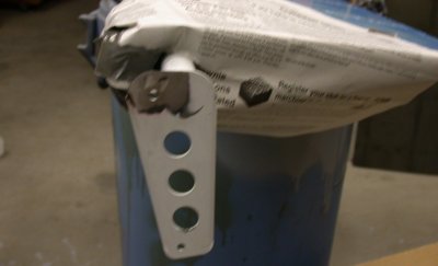
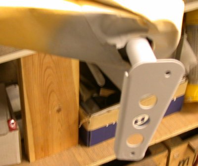
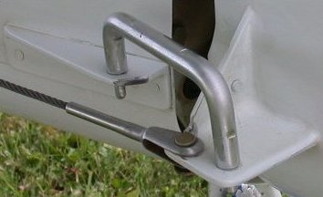 My rudder lock
will be similar to this one I saw at OSH, although mine will have a WARNING
FLAG. Note how this builder apparently used body filler to fill in all
the seams and joints around the rudder horn, so it looks like it's all one
piece. It looks real nice, but I don't want to get involved in all the
time, effort, and weight doing this all over the plane would involve.
My rudder lock
will be similar to this one I saw at OSH, although mine will have a WARNING
FLAG. Note how this builder apparently used body filler to fill in all
the seams and joints around the rudder horn, so it looks like it's all one
piece. It looks real nice, but I don't want to get involved in all the
time, effort, and weight doing this all over the plane would involve.
Aug 12 - Countersink the rudder stops. Receive and inventory my Angle of Attack system. Talk to Van's about the double row of rivets at the aft fuseleage 712 A & B rear bulkhead. Tom said they're just left out of the QB for taildragger guys, so I can go ahead and rivet them up with the rudder stops. Prime rudder stops. Removed rudder, then decided to reinstall it and adjust the rudder cables. Removed and reinstalled the rudder cables a couple times, until I got the sequence right. The clevis end is to the REAR, and you have to install the cable by threading it from the REAR. Installed rudder cables and bushings. Rivet the rudder stops into place. One rudder stop pop rivet location needs longer than the CS4-4 called for in the plans. Wrote Van's about using a CR 3212-4-6 instead. They said it is fine. Removed rudder and V-stab so I could install F-712A/B rivets. Squeezed rudder stop aft F-712B rivets. Holes seemed a bit large for -3 rivets, but too small for -4, and plans say to use -3. 6.0 hr
 Here are
the rudder stops, countersunk and ready for primer and installation.
Here are
the rudder stops, countersunk and ready for primer and installation.
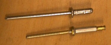 This
is the difference between the plans-specified CS4-4 (top) and the much
higher quality CR3212-4-6 Cherrymax structural rivet. I need the
longer reach for one of the pop rivets on each rudder stop.
This
is the difference between the plans-specified CS4-4 (top) and the much
higher quality CR3212-4-6 Cherrymax structural rivet. I need the
longer reach for one of the pop rivets on each rudder stop.
Aug 13 - Put in pop rivets for rudder stop. Van's replied and said CR3212-4-6 is more than equal replacement for CS4-4, so I put in the CR3212 pop rivets for the rudder stops. The head sat in the countersunk holes so much better than the CS4-4s did that I decided to use CR3212-4-6 for both fwd pop rivet locations on each rudder stop. Ordered more CR3212-4-6 pop rivets and some other stuff from Van's. Found out later they cost $1.10 each , as opposed to .05 for CS4-4 and fractions of a penny for solid rivets, so I guess they must be better!
Worked on setting elevator stops. Up needs to be 25-30 degrees and down needs to be 20-25 degrees. Up elevator stop is already at 30 degrees, as I installed it, but the down elevator stop needed to be trimmed quite a bit to get 23 degrees of down travel.
I started rigging the elevator pushrod. Remember, I cut it 1" too short awhile back. Van's told me to wait & see if it would work anyway. As it turns out, only 8 threads engage on each end - about 5/16" out of 1 1/8" of threads (it's supposed to be over half the threads engaged). I wrote to Van's about that. They said I could make it work if I make the elevator bellcrank a few degrees out of perfectly vertical to get 3/8" of threads engaged, but I think I will just bit the bullet and order a new tubing piece and do it right. 4.5 hr
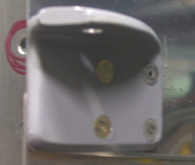 The 2 fwd rivets (RT in this pic) are supposed to be CS4-4 pop rivets, as
per the plans. The lower one needed a longer rivet than the CS4-4, so
I used a CR3212-4-6 instead. Not only are the CR Cherry Max rivets
much stronger (and much more expensive), they also sit much better in the
countersink holes, as you can see here. I will replace both upper fwd
pop rivets with the CR3212-4-6 rivets, when my next parts order from Van's comes in.
The 2 fwd rivets (RT in this pic) are supposed to be CS4-4 pop rivets, as
per the plans. The lower one needed a longer rivet than the CS4-4, so
I used a CR3212-4-6 instead. Not only are the CR Cherry Max rivets
much stronger (and much more expensive), they also sit much better in the
countersink holes, as you can see here. I will replace both upper fwd
pop rivets with the CR3212-4-6 rivets, when my next parts order from Van's comes in.
 This
shows how much (all of it) of the down elevator stop I had to grind away to
get the proper elevator down travel. This shows the RT side done, with
the LT side still left to be done.
This
shows how much (all of it) of the down elevator stop I had to grind away to
get the proper elevator down travel. This shows the RT side done, with
the LT side still left to be done.
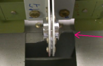
 This pic shows how much of the down stop I had to trim to get my down travel
right. The blue lines show the original line of the stop. I
ended up going all the way forward and into the skin some. I had to
take a little more off the LT than the RT so both elevator horns were
hitting at the same time.
This pic shows how much of the down stop I had to trim to get my down travel
right. The blue lines show the original line of the stop. I
ended up going all the way forward and into the skin some. I had to
take a little more off the LT than the RT so both elevator horns were
hitting at the same time.
Aug 21 - Been away working for a week. Back to the plane. Back to FUSELAGE while waiting for the aft elevator rod to come in, then I'll finish the empennage setup.
GO TO SEPTEMBER empennage
BACK TO MY RV BUILDER'S HOME
BACK TO BRIAN'S HOME