June 2 - received Van's order -
more 0.063" plates for elevator servo mount, rod, rod end jam nuts,
misc hardware. Started laying out plate for elevator servo.
Battling lots of mosquitoes and caterpillas. Laying out the
elevator servo makes me realize that the servo arm being perpendicular to
the ROD, not the BASE, at neutral position is what's important. Bend,
cut, trim plate to fit. Received ACS order - Cherrymax rivets,
including the 125 CR3242-4-4 oversized rivets to fix the cabin frame.
Start drilling out rivets in fuselage bottom. Drill & cleco plate
into bottom rivet holes. Trimmed plate some. Just as I foolishly
tried to JUMP on the shear, trying for a cleaner cut with less movement, my
hand slipped and I cut a bunch more off the plate than I'd intended
to. That was a dumb move. I thought the plate was trashed, but, as the dimensions were
rather arbitrary, I found I could still use it. I lost about half an
inch at one end and 1/4" at the other. 6.0
hr
Here is the initial layout for the elevator autopilot servo. Others
have rigged up frames that put the servo more forward, on top of the middle
rib, but it seemed to me that it raised the servo above the optimal
location, put the servo awfully close to the aft elevator pushrod, and
required more bracing. So, the weight is a bit more aft, and it takes
a longer actuating rod, but this seemed to me to be the best placement,
after much pondering & holding the servo in different places.
I decided to put the servo rod end on the elevator bellcrank at the point
between the 2 rivets, where there is already a spacer plate between the 2
halves of the bellcrank.
Here is the elevator servo sitting in place, with a temporary actuating rod,
sitting on the 0.063 T2024T3 mounting plate. The mounting plate is
flanged up to mate with the back of the bulkhead. The rod shown here
is one I quickly made, without trying to do a great job drilling and tapping
the ends, as I plan to use a bigger rod for this length. Yet, these 2
"quick & dirty" drill & tap jobs came out with the rod end
bearing threads tighter than the careful ones I made for the aileron servo!
June 3 - Drill main lightening
hole in elevator servo mount plate. I will drill more, smaller, holes,
once I get the rivet pattern laid out. Realized that I need a
triangular plate to tie the mount plate into the vertical angle for my
custom baggage area, and I will need a filler plate to bridge the thickness
between the fuselage bulkhead and the outer surface of the mount plate and
the vertical angle. So, I made patterns for those 2 plates, and
fabricated them. Drilled out the lower bulkhead rivets to tie these
plates into the bulkhead. Due to the awkward angles I was working in,
leaning over into the fuselage, some of the rivets drilled out OK, and some
ended up with enlarged holes. A couple, one in particular, were rather
severely enlarged. So, I added some 5/32" and even some oversized
5/32" CherryMax rivets to the NEXT order I am putting together for
ACS. Countersunk the outer perimeter rivet holes in the mount
plate. 5.0 hr
The elevator servo mounting plate has a flange that ties it into the
fuselage bulkhead. The smaller plate provides a spacer between the
bulkhead, the main plate flange, and the vertical angle for my custom
baggage area. The larger plate then ties them all together. Here
are the patterns and the 2 plates.
Here is the main elevator servo mounting plate, laid in place. The fwd flange ties it
into the bulkhead, at the bottom of this pic, and I drilled out rivets in the fuselage panels, on the
RT in this pic, to tie the plate into them. The 2 plates shown in the
previous pic will tie into the main plate flange, the bulkhead, and the
vertical bar for the custom baggage area, shown in the lower LT in this
pic. The initial lightening
holes here showed me a gap between this flat plate and the slightly curved
fuselage bottom, so I knew I'd have to bend this plate some to match the
fuselage skin curve. This also made me aware that, when I did the
aileron servo plates on the RT wing, I hadn't noticed or thought about the
curve, so I had to go back and examine that. See the Wings
page for details on that.
June 4 - I'm still trying to
figure out how I'm going to resolve the difference between the flat plate
and the curved fuselage bottom skin. I hadn't really noticed it when I
did the wing servo, but I went back to the wing and I can see where the
slight curve in the skin has been flattened by the plates
there. It's from
the spar going about 9" aft, in the 4th bay from outboard.
This isn't good, as the wing curve is more critical than the fuselage
curve. I called Van's about it, and Ken said don't worry about such a
slight flattening. He said if it was so small (maybe 1/16") a
flattening that I didn't notice it as I was doing it, and it's only 9"
length between 2 ribs, it won't affect flying. He also suggested
fluting my elevator servo plate, so I tried that. It didn't work; that
0.063" plate is just too stiff. So, I placed an order to Avery
for a forming bag and forming hammer. I
found out later I could have gotten the shot bag from Kent White at TM
Technologies for about half what I paid Avery. I also put together yet another
order to ACS for even MORE Cherrymax rivets. Those things are
expensive, but they sure get the job done! Received my
Cleaveland order of dies, and recieved another ACS order, with my heavier
actuating rod material for the elevator servo, more CherryMax rivets, and
some servo mounting hardware (AN509 screws). 2.5
hr
I tried fluting the plate flange as much as I could. It didn't seem to
make any difference, so I knew I'd have to get a forming bag and hammer, and
hammer a curve into it. See tools page.
June 6 - Reassembled the cabin
frame, with the CherryMax CR3242-4-4 oversized shank rivets I
received. Made sure the frame was securely clamped to the table this
time! Worked on fitting the new (straight) cabin frame. Made a
new F632A channel. Ground the F631C/D assy inner upright arm, for a
better fit with the new, straight frame. Fit, drill, cleco new F632A
channel and F732Cs. I was able to reuse the old F732C brackets.
Got cranking & worked until 0330. 6.0 hr
Putting in the CR3242-4-4 oversized 1/8" CherryMax rivets. Note
that there is less emphasis on clecoes, and much more emphasis on clamping
this thing flat, during this riveting process. When I was done, it
remained nice & flat.
June 7 - Finish drilling &
clecoing F632A holes. Remove, clean, polish, prime new F632A
channel. Rivet F732E brackets. Vacuum metal chips out of
fuselage. Cleco F774 top skin on, to see how it fits with the F631C/D
brackets. 2.0 hr
Here
is the F774 top skin, temporarily clecoed into place, to see how the skin
will line up with the F631C/D brackets. I can't really finish the
cabin frame any more, because I have to put in those 4 top skin rivets
BEFORE I install the F732B angle, and I can't do the F632A until I do that,
and I can't do the frame until the F632A is done (otherwise it won't fit
in), so the whole thing is on hold until I get that skin done. And I
won't attempt to do the skin and close in that area until my elevator servo
and custom baggage area are all completely done.
June 8 - Received Avery order with
shot bag and forming hammer. Received ACS order with still more
CherryMax rivets and shorter (-S56) AN509-10R14 screws for elevator servo
mount (only 1 plate to go through). Went to gun shop, got 50 pounds of
#8 lead shot for shot bag, and filled shot bag . Used shot bag & forming hammer on elevator servo mount
plate. It only took a few hits to kinda overdo it a bit. It's
still very hard to get any sort of curve along the flange, where it's VERY
stiff. Instead, it tended to bend parallel to the flange, causing the
flange to bend in so it's more than 90 degrees from plate. Hammered,
tweaked, bent, teased the plate until I had it about right. 1.5
hr
June 9 - clean up shop 2.0
hr
June 10 - Another long weekend at the track.
Work on updating web site (process the last
several weeks' photos) 3.0 hr doc
June 11 - work on updating web site (add pics &
captions to pages) 6.5
hr doc
June 12 - Spent most of the day at the New England
Van's Air Force Fly-In at Lawrence, MA airport. It was nice, and I
attended 3 interesting seminars. I was surprised there weren't more
RVs there, though; only 2 planes with tipup canopy. Continue updating web site with last several weeks'
work 3.0 hr doc
June 13 - continue updating web site during down time
at the track 7.5 hr doc
June 16 - resume fitting elevator
servo mount plate to bottom skin. Spent a bunch of time agonizing over
the rivet layout. Finally decided on rivet layout, and drilled the
rivet holes in the plate. Started drilling & clecoing plates into
place. 3.0 hr
June 17 - Spent most of the
afternoon working on my application and audition video for SURVIVOR
10. I had also applied to SURVIVOR 8, but never heard from them. Finished drilling and clecoing the servo mount plates. All
the holes that go through the bulkhead and custom baggage area upright angle
are drilled to 11/64" for the oversized 5/32" CherryMax
rivets. This is because it was very difficult to get good access to
the rivets that were already there, and so I significantly
enlarged the holes when I drilled out the existing 1/8" rivets. 1.5
hr
June 18 - Drill lightening holes
in the elevator servo mount plates, drill and countersink servo mount holes,
debur plates. Clean, paint prep, and prime plates. 3.75
hr
This is the main elevator servo attach plate, with all the rivet holes and
lightening holes drilled. I am in the process of countersinking the
servo attach screw holes here. The dimpled sample at the top is what I
use to make sure the counersink is deep enough. The blue piece is a
piece of scrap 0.063" plate I temporarily clecoed to the servo plate,
in order countersink the screw hole enough to accept the dimpled skin, and
keep a tight pilot hole at the same time. Without the backing plate,
as I found on my wing servo mount plates, the hole gets enlarged and you
lose the pilot effect without a backing plate. The red circle shows
the area enlarged in the next pic, for more clarity.
You can see in this detail shot that, in order to get the countersink deep
enough to accept the dimpled skin nice & flat, you are enlarging the
hole (you can see the blue plastic on the bottom plate here), and you will
lose your countersink pilot and end up with a screwed up, out of shape
hole. So, to prevent that, you need the backing plate.
June 19 - Dimple fuselage bottom
skin for servo mount plate, cleco plates into place. Found that the
holes for the CR3242-5-4 CherryMax rivets are too small. 0.75
hr
June 20 - Redrill the plate
flanges with #16 drill for CR3242-5-4 CherryMax rivets. Install the
CherryMax rivets. Found out that, because I was focusing on the
flange-to-bulkhead rivets and didn't also cleco the outer edge of the plate
to the fuselage skin panel overlap holes, the outer edge holes don't line up
right. Drill out the 4 CR3242-5-4 CherryMax rivets-not a pretty
sight. It's very hard to get access in there, so I am working at a
significant handicap (hard to see, hard to reach) when trying to drill out
rivets there. Now, it looks like the holes are enlarged to the point
where I will have to use solid 3/8" rivets in those 4 holes. I
finally got the plate fully clecoed in and all the holes lined up and
drilled. Two of them had to go to 3/8", and the rest of all the
big holes (everything where the flange attaches to the bulkhead junction and
the baggage compartment vertical post) were OK at #16 drill
(CR3242-5-4). Squeezed the two 3/8" rivets in place and installed
the CherryMax rivets. Then Karla helped me drive the 3/32" rivets
through the fuselage bottom skin. I was using -4.5 rivets, but they
were bending over, so I switched to -4s, and it went better. Karla's
arms were fading toward the end, and not holding the gun tight to the skin,
so several of them (about half, actually, between hers that were too loose
and mine that were too long) had to be drilled out and redone. Drilled
out the rivets, let Karla rest, and re-drove some of them. The length
seems marginally too short (shop heads either too narrow or too low), but
the skin thickness measurements indicate a -4 and if I try to use 4.5s, they
bend over. Anyway, we finally got it done satisfactorily. 5.75
hr
Here are the 3 elevator servo plates, primed and ready to install.
The elevator servo mount plates are all clecoed into place, ready for
riveting. The LT side of the pic is the vertical post for the custom
baggage compartment, made of 0.063" angle. At the lower LT of the
pic is the custom baggage compartment bottom panel, made from 0.016"
6061T6. The upper panels are made from 0.032" 6061T6.
June 21 - Cleco custom baggage
compartment panels in. Fabricate rivet protrusion gage on the
mill. Squeeze all the custom baggage compartment rivets I can reach,
and drive the rest by myself, by putting the cupped set on a bucking bar and
using the back rivet tool on the gun. Karla helped rivet the ones I
couldn't do with the 2 previous methods. Two rivets had to be drilled
out and replaced with pop rivets. 5.75 hr
Here's the LT side of the custom baggage compartment, looking aft, with the
pieces clecoed and ready to rivet. The elevator autopilot servo is in
the background of the LT side (RT in the pic). The light gray round
thing on the far LT in the pic is the rudder cable protection tube, that
keeps anything in the custom baggage compartment from touching the rudder
cable.
And
here's the RT side view, looking aft, showing the actual custom baggage
compartment area. The aft portion of the compartment has a panel that
is held in with screws, so it can be removed if necessary.
Here's
a pic of a rivet protrusion gage I made from 5/16"
aluminum stock. One end shows how much should be protruding (before
riveting) for 3/32" rivets and the other end is for 1/8"
rivets. I just set up a chunk in my mill, milled the bottom smooth,
then dropped the cutter 9/64" for one end and 3/16" for the other
end (1.5 times rivet diameter).
This is
actually made for putting dimple dies into the gun part and the bucking bar
part, and making dimples where you can't get access otherwise. Here,
the bucking bar part is set up to use for setting 470 rivets while I use a
back rivet tool in the gun. It was much easier to do it this way, for
the baggage compartment panel rivets I couldn't squeeze, than to use a
regular cupped set in the gun and a plain bucking bar, because I could only
see one side at a time of what I was working on. I taped some scrap
aluminum pieces to the other end so that, when they are sitting flat on the
work, I can feel the bucking bar is parallel with the work, without having
to see it. The pieces under the tape are also a bit wider than the bar
itself, so that helps stabilize the bar and keep it from rocking.
I used
the lathe to trim the elevator autopilot servo control rod to length.
June 22 - received latest ACS order
June 23 - Drive 3/8" rivets
for custom baggage compartment frame angle intersections. I was
originally going to use AN3 bolts there, but after the success using the
solid 3/8" rivets on the elevator servo plate flange, I decided to use
solid rivets for the intersections. Karla helped drive the last
remaining plate rivet, and helped me mount the elevator servo and install
the 4 AN3 screws holding it in. Torqued the elevator servo mount
screws. 2.25 hr
Here
is the elevator autopilot servo, mounted and torqued. The actuating
rod is still temporarily fastened. Just above & below where the
rod crosses over the bulkhead, you can see the 2 solid 470-6 rivets I had to
use, because the holes got so enlarged from trying to drill out the rivets
down in there. The upper one is also going through the upright angle
for the custom baggage compartment. The rest of the rivets you see
going through the bulkhead, along the servo plate flange, are CR3242-5-2
oversized 5/32" CherryMax rivets.
June 24 - clean up shop &
bench. Spent some time trying to find a clever place to put the servo
controller. Perhaps on the elevator bellcrank rib? Also looked
over the sizing and placement of my planned custom fuselage access panels.
Laid out potential cut lines in top of side fuse skin. 1.75
hr
June 25 - clean up shop &
bench. Drill out temp pop rivets in aft fuse bulkhead. Remove
and file outer edges of F631 C/D angles again, for a better fit with the
skin that lays on them. Re-countersink F631C/D outer angles again,
after changing surface in the previous step. Reinstall & torque
F631C/D brackets. Start looking at front deck again. Start
fabricating the F644 R&L, F768D R&L, F768C, F721C R&L, F703C
R&L, F743B brackets. Trim F697 and F643-1 pieces. I need to
contact Van's to see if I can make the F703B from 6061, as that's what I
have, having used the angle I got in the kit on my custom baggage
compartment. I need to make sure they are not using 2024 for
this. The F643-1 has one angle at 90 degrees and one not at 90
degrees. I measured wrong, and ended up with the F643-1 cut 1/16"
too short, and cut at 90 degrees on the non-90 degree side. The
90 degree trim cut needs to be on the same flange as the formed 90 degree
angle. Decided to make a shim to make up the 1/16", rather than
order a new F643-1. 5.75 hr
LOTS of
brackets to fabricate for the subframe. These are from DWG 24A.
There were a couple more, not shown here, from DWG 24.
A couple
more pieces to fabricate. The little piece is a shim plate I had to
make from 0.063" because I ended up with the F643-1 cut 1/16" too
short. I later found out the F697 is cut wrong, so don't cut yours
like this.
June 26 - make trim cuts to F703C
and F721C brackets. Drill holes in F703C and F721C. 1.75
hr
June 27 - I noticed the gear legs
are starting to get a little rusty. Spray LPS-3 onto them. Use
thread chaser on RT gear leg to clean up threads, so nut will go on
smoothly. At first, I thought I'd made the F703C brackets wrong, as
they would not line up with holes in instrument panel. But then I
figured out that the panel goes on the OUTside of the F703Cs, not the INside.
Cleco F703C L&R angles to F703 instrument panel. Found out that I
had interpreted the dotted lines in the F697 as being the legs, with it
trimmed back TOWARD the legs, but what became apparent was that I should
have trimmed AWAY from the legs. The drawing does not provide an end
view, and should. So, if you're following this, MAKE SURE YOU TRIM THE
F697 SO THE LEGS ARE LONGER, NOT SHORTER, THAN THE REST OF THE PIECE.
I will have to order a new F697. Spent lots of time dicking around
trying to get the F644 L&R aligned, clamped into position, and drilled
properly. The LT side had lots of problems, and I kept having to
enlarge the hole so the angle would be parallel to the tops of the center
sub-panel. I ended up with 3/8" holes on the LT side. I
found some flush head 3/8" rivets in my old bag of rivets, so I will
use them for the LT F644. Lay out F768C center seal support.
Flute F768C to match top of F768A center sub-panel. Clamp F768C in
position 1/8" below the top of the F768A. Drill and cleco F768C
to F768A. 6.0 hr
Here's
the F697 I cut, and the drawing it's based on. It sure seems to me that
the dotted line represents the legs, and they don't provide an end view, so I
made it like this. I later figured out, from looking at the iso
drawing and seeing where the F697 was going to mount, that it's wrong.
The legs are DOWN when the cut is made. I suggested to Van's that they
clarify the drawing, but the guy I was talking to at the time said I should
been able to figure it out by also looking at the isometric drawing.
They also
don't provide an end view for the F644, so I interpreted that wrong,
too. But it didn't matter, as I just switched LT & RT, and then
they matched up.
This shows
how the F643 end had to be recut, using the CORRECT side as the 90 degree
angle, because it's a wedge shape.
This pic shows
the F643 cut properly - with the 90 degree cuts at both ends on the SAME
SIDE. I had initially made my 90 cut (on RT in this pic) at 90 degrees
with the top flange in this pic. That flange is not 90 degrees at the
other end (LT in this pic), so it lost me 1/16", which I had to make up
by using the shim you see super-glued on to the LT end flange in this pic.
Here is the LT
F644 clecoed in place. As you can see here, the upper one has been
enlarged to 3/16" and the bottom one is 5/32", due to having a
hard time getting it clamped properly and aligned both with the tops of the
center subpanel (C) and outboard subpanel (D), as well as being at the right
angle so the top of it (A) is flush with the top of the F745 (B).
Here is the
F768C, center seal support, clamped into place against the F768A, center
subpanel.
June 28 - Sort out all my
threaded drill bits. It's been too much trouble searching through the
drawer of them every time I need to use the angle drill. Start working
on F768D L&R outboard seal supports; lay out and drill rivet
holes. Lay out and cut bending slots on F768D L&R. Smooth
& polish bending slots. Call Van's. They said the angle they
use is 6061, so what I have will work for the F703B. They also said
TSCB about the way the F697 is depicted on the drawing. Oh well.
I ordered a new F697 by 2nd Day Air. Bent the F768D L&R seal
supports to fit the tops of the F768B L&R outboard sub-panels. Cut
F703B to length. Drill & cleco F768D L&R to F768B
L&R. Lay out F703B. Make bending cuts in F703B. Smooth
out all the cuts in the F703B and bend it to fit the outline of the top of
the instrument panel. Clamp, drill, cleco F703B to instrument
panel. 10.0 hr
Here are the F768D
outboard seal supports, cut and ready to match to the outline of the F768B
outboard subpanels.
The DAR
at the Lawrence, MA fly-in suggested I include pics showing ME with the
plane occasionally, just to prove it's really me working on this
plane. Yep, that does appear to be me, all right, just stopping in to
observe what my plane building slaves have accomplished so far ;-)
I
went through my drawer of threaded drill bits and sorted them out, so it
doesn't take 15 minutes every time I need to find a specific diameter and length
bit. I left 'em here, cuz I haven't yet figured out a good mechanism
to keep them stored sorted.
I made this
little 1/8" thick gage from 2 pieces of 0.063" scrap superglued
together, to easily gage when the tops of the seal supports are the correct
1/8" below the subpanel top flange.
Here is one
end of the F703B, after all the bending cuts have been made and I'm starting
to bend it to match the contour of the top of the instrument panel.
Here are the 3
seal supports after being bent to match the contour of the tops of the
subpanel, and drilled and clecoed into place.
Here, I am
just starting to clamp the F703B to the top of the instrument panel, working
my way out from the center, and bending the F703B as I go, to match the
contour of the instrument panel. In the center foreground, you see the
RT F703C angle clecoed in place.
June 29 - Finish clamping,
drilling, & clecoing F703B to instrument panel. Dimple, clean,
prime, rivet F644 L&R. Clean, prime, rivet F768C, F768D L&R,
and F743B. Clean up some of the mess. Drill & cleco F768Bs
to F745s. Clean, prime, flush rivet F768Bs to F745s. Fabricate
F721D L&R brackets. 9.25 hr
This shows
the two 426-6 rivets I had to use on the LT F644, because I'd had to enlarge
my initial holes some, to get the F644 positioned correctly. I guess
these oughta hold it!
Here's
the F786A center subpanel, with the two F644s riveted on.
and here is one of the 2 outboard subpanel assemblies, with the seal support
riveted on
Here is the
F703 instrument panel, with the F703B and F703C support angles clecoed on.
June 30 - Realize I'd made the
F721D L&R brackets from .063 angle, when they should have been from .032
angle. Made new F721Ds. Fabricate F793 L&R brackets.
Lots of brackets!! Realized I'd muffed the radius cut and holes on the
LT F793, due to all the oddball dimensions they used. Remade the LT
F793. While remaking the LT F793, realized the RT one isn't exactly
right, either. It's all these odd combinations of 9, 11, 13 32nds from
different edges. I calculated the 1 7/16" radius cut center should be 1 49/64" from the
rivet hole centers. Finally got both F793 brackets reasonably close,
even though I had taken great pains to mark the 2 rivet holes
precisely. Once drilled, the 2 holes aren't exactly where I marked
them; they're off by 2-3 64ths. Grrrr. Oh well;
should be close enough. Received new F697 from Van's. Started
laying it out (right this time). Cut & smooth F697. Drill
& cleco F697 into place. Drill & cleco F643-1. Clean,
prep, prime F643-1, F697, F768 assy. Rivet F643-1 and F697 to F768
assy. Cleco outboard F768 subpanel assemblies to fuselage. Cleco
center F768 subpanel assy in. Mark centerline on F643-1 rib top
flange, F644 rib top flange, firewall top flange. Cleco F771 fwd skin
on. Match drill F771 to F643-1 and F644 rib flanges. Match drill
F771 skin to firewall flange. Match drill F771 skin to F768 assy top
flanges. Match drill F743B to firewall. Fit F721C & D angles
(RT), and drill for nutplates. 13.0 hr
This
partially shows the layout for the F793 brackets. The drawing for this
didn't give dimensions for where to center the 1 7/16" arc cut, but the
drawing was full scale, fortunately, so I measured it directly on the
print. I came up with 1 49/64" from each rivet hole. So, I
clamped the F793 to the bench and used the dividers to lay it out.
Here
are the new F697 (correctly cut this time) and the F643-1 clecoed onto the
growing center subpanel assy. I still don't understand why that F697
is shaped that way. I am hoping it will become apparent at some point
here.
This pic
shows the subpanel completely assembled, and about 3/4 of the way through
clecoing the F771 skin on over it. The top flanges of the F644 and
F643 ribs were marked with center lines, and match drilled to the skin as
part of this. The bottom edge, where the top skin joins the side skin,
sure didn't want to bend down and be clecoed. My wingnut clecoes sure
helped with that. You can barely see one, as the second from the LT on
the bottom here.
During the summer, I
sometimes get huge moths coming in. This one's wingspan was about
6-8"
 Here is the initial layout for the elevator autopilot servo. Others
have rigged up frames that put the servo more forward, on top of the middle
rib, but it seemed to me that it raised the servo above the optimal
location, put the servo awfully close to the aft elevator pushrod, and
required more bracing. So, the weight is a bit more aft, and it takes
a longer actuating rod, but this seemed to me to be the best placement,
after much pondering & holding the servo in different places.
Here is the initial layout for the elevator autopilot servo. Others
have rigged up frames that put the servo more forward, on top of the middle
rib, but it seemed to me that it raised the servo above the optimal
location, put the servo awfully close to the aft elevator pushrod, and
required more bracing. So, the weight is a bit more aft, and it takes
a longer actuating rod, but this seemed to me to be the best placement,
after much pondering & holding the servo in different places. I decided to put the servo rod end on the elevator bellcrank at the point
between the 2 rivets, where there is already a spacer plate between the 2
halves of the bellcrank.
I decided to put the servo rod end on the elevator bellcrank at the point
between the 2 rivets, where there is already a spacer plate between the 2
halves of the bellcrank. Here is the elevator servo sitting in place, with a temporary actuating rod,
sitting on the 0.063 T2024T3 mounting plate. The mounting plate is
flanged up to mate with the back of the bulkhead. The rod shown here
is one I quickly made, without trying to do a great job drilling and tapping
the ends, as I plan to use a bigger rod for this length. Yet, these 2
"quick & dirty" drill & tap jobs came out with the rod end
bearing threads tighter than the careful ones I made for the aileron servo!
Here is the elevator servo sitting in place, with a temporary actuating rod,
sitting on the 0.063 T2024T3 mounting plate. The mounting plate is
flanged up to mate with the back of the bulkhead. The rod shown here
is one I quickly made, without trying to do a great job drilling and tapping
the ends, as I plan to use a bigger rod for this length. Yet, these 2
"quick & dirty" drill & tap jobs came out with the rod end
bearing threads tighter than the careful ones I made for the aileron servo! The elevator servo mounting plate has a flange that ties it into the
fuselage bulkhead. The smaller plate provides a spacer between the
bulkhead, the main plate flange, and the vertical angle for my custom
baggage area. The larger plate then ties them all together. Here
are the patterns and the 2 plates.
The elevator servo mounting plate has a flange that ties it into the
fuselage bulkhead. The smaller plate provides a spacer between the
bulkhead, the main plate flange, and the vertical angle for my custom
baggage area. The larger plate then ties them all together. Here
are the patterns and the 2 plates.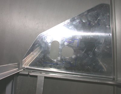 Here is the main elevator servo mounting plate, laid in place. The fwd flange ties it
into the bulkhead, at the bottom of this pic, and I drilled out rivets in the fuselage panels, on the
RT in this pic, to tie the plate into them. The 2 plates shown in the
previous pic will tie into the main plate flange, the bulkhead, and the
vertical bar for the custom baggage area, shown in the lower LT in this
pic. The initial lightening
holes here showed me a gap between this flat plate and the slightly curved
fuselage bottom, so I knew I'd have to bend this plate some to match the
fuselage skin curve. This also made me aware that, when I did the
aileron servo plates on the RT wing, I hadn't noticed or thought about the
curve, so I had to go back and examine that. See the
Here is the main elevator servo mounting plate, laid in place. The fwd flange ties it
into the bulkhead, at the bottom of this pic, and I drilled out rivets in the fuselage panels, on the
RT in this pic, to tie the plate into them. The 2 plates shown in the
previous pic will tie into the main plate flange, the bulkhead, and the
vertical bar for the custom baggage area, shown in the lower LT in this
pic. The initial lightening
holes here showed me a gap between this flat plate and the slightly curved
fuselage bottom, so I knew I'd have to bend this plate some to match the
fuselage skin curve. This also made me aware that, when I did the
aileron servo plates on the RT wing, I hadn't noticed or thought about the
curve, so I had to go back and examine that. See the 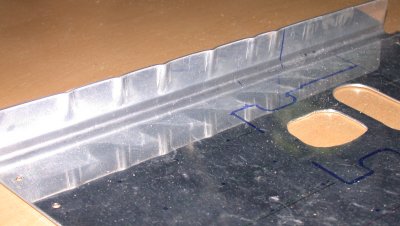 I tried fluting the plate flange as much as I could. It didn't seem to
make any difference, so I knew I'd have to get a forming bag and hammer, and
hammer a curve into it. See
I tried fluting the plate flange as much as I could. It didn't seem to
make any difference, so I knew I'd have to get a forming bag and hammer, and
hammer a curve into it. See  Putting in the CR3242-4-4 oversized 1/8" CherryMax rivets. Note
that there is less emphasis on clecoes, and much more emphasis on clamping
this thing flat, during this riveting process. When I was done, it
remained nice & flat.
Putting in the CR3242-4-4 oversized 1/8" CherryMax rivets. Note
that there is less emphasis on clecoes, and much more emphasis on clamping
this thing flat, during this riveting process. When I was done, it
remained nice & flat. Here
is the F774 top skin, temporarily clecoed into place, to see how the skin
will line up with the F631C/D brackets. I can't really finish the
cabin frame any more, because I have to put in those 4 top skin rivets
BEFORE I install the F732B angle, and I can't do the F632A until I do that,
and I can't do the frame until the F632A is done (otherwise it won't fit
in), so the whole thing is on hold until I get that skin done. And I
won't attempt to do the skin and close in that area until my elevator servo
and custom baggage area are all completely done.
Here
is the F774 top skin, temporarily clecoed into place, to see how the skin
will line up with the F631C/D brackets. I can't really finish the
cabin frame any more, because I have to put in those 4 top skin rivets
BEFORE I install the F732B angle, and I can't do the F632A until I do that,
and I can't do the frame until the F632A is done (otherwise it won't fit
in), so the whole thing is on hold until I get that skin done. And I
won't attempt to do the skin and close in that area until my elevator servo
and custom baggage area are all completely done.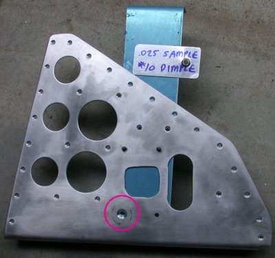 This is the main elevator servo attach plate, with all the rivet holes and
lightening holes drilled. I am in the process of countersinking the
servo attach screw holes here. The dimpled sample at the top is what I
use to make sure the counersink is deep enough. The blue piece is a
piece of scrap 0.063" plate I temporarily clecoed to the servo plate,
in order countersink the screw hole enough to accept the dimpled skin, and
keep a tight pilot hole at the same time. Without the backing plate,
as I found on my wing servo mount plates, the hole gets enlarged and you
lose the pilot effect without a backing plate. The red circle shows
the area enlarged in the next pic, for more clarity.
This is the main elevator servo attach plate, with all the rivet holes and
lightening holes drilled. I am in the process of countersinking the
servo attach screw holes here. The dimpled sample at the top is what I
use to make sure the counersink is deep enough. The blue piece is a
piece of scrap 0.063" plate I temporarily clecoed to the servo plate,
in order countersink the screw hole enough to accept the dimpled skin, and
keep a tight pilot hole at the same time. Without the backing plate,
as I found on my wing servo mount plates, the hole gets enlarged and you
lose the pilot effect without a backing plate. The red circle shows
the area enlarged in the next pic, for more clarity.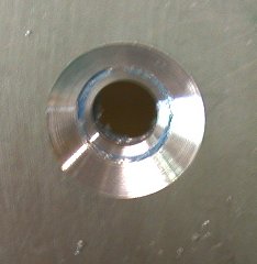 You can see in this detail shot that, in order to get the countersink deep
enough to accept the dimpled skin nice & flat, you are enlarging the
hole (you can see the blue plastic on the bottom plate here), and you will
lose your countersink pilot and end up with a screwed up, out of shape
hole. So, to prevent that, you need the backing plate.
You can see in this detail shot that, in order to get the countersink deep
enough to accept the dimpled skin nice & flat, you are enlarging the
hole (you can see the blue plastic on the bottom plate here), and you will
lose your countersink pilot and end up with a screwed up, out of shape
hole. So, to prevent that, you need the backing plate.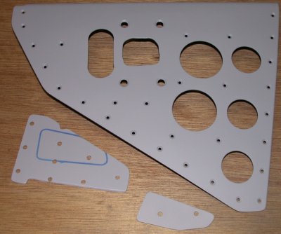 Here are the 3 elevator servo plates, primed and ready to install.
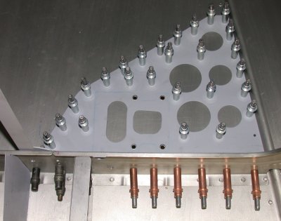 The elevator servo mount plates are all clecoed into place, ready for
riveting. The LT side of the pic is the vertical post for the custom
baggage compartment, made of 0.063" angle. At the lower LT of the
pic is the custom baggage compartment bottom panel, made from 0.016"
6061T6. The upper panels are made from 0.032" 6061T6.
The elevator servo mount plates are all clecoed into place, ready for
riveting. The LT side of the pic is the vertical post for the custom
baggage compartment, made of 0.063" angle. At the lower LT of the
pic is the custom baggage compartment bottom panel, made from 0.016"
6061T6. The upper panels are made from 0.032" 6061T6.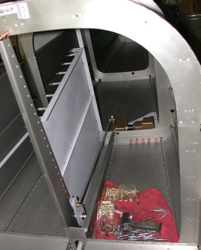 Here's the LT side of the custom baggage compartment, looking aft, with the
pieces clecoed and ready to rivet. The elevator autopilot servo is in
the background of the LT side (RT in the pic). The light gray round
thing on the far LT in the pic is the rudder cable protection tube, that
keeps anything in the custom baggage compartment from touching the rudder
cable.
Here's the LT side of the custom baggage compartment, looking aft, with the
pieces clecoed and ready to rivet. The elevator autopilot servo is in
the background of the LT side (RT in the pic). The light gray round
thing on the far LT in the pic is the rudder cable protection tube, that
keeps anything in the custom baggage compartment from touching the rudder
cable.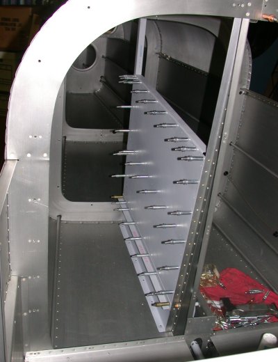 And
here's the RT side view, looking aft, showing the actual custom baggage
compartment area. The aft portion of the compartment has a panel that
is held in with screws, so it can be removed if necessary.
And
here's the RT side view, looking aft, showing the actual custom baggage
compartment area. The aft portion of the compartment has a panel that
is held in with screws, so it can be removed if necessary. Here's
a pic of a rivet protrusion gage I made from 5/16"
aluminum stock. One end shows how much should be protruding (before
riveting) for 3/32" rivets and the other end is for 1/8"
rivets. I just set up a chunk in my mill, milled the bottom smooth,
then dropped the cutter 9/64" for one end and 3/16" for the other
end (1.5 times rivet diameter).
Here's
a pic of a rivet protrusion gage I made from 5/16"
aluminum stock. One end shows how much should be protruding (before
riveting) for 3/32" rivets and the other end is for 1/8"
rivets. I just set up a chunk in my mill, milled the bottom smooth,
then dropped the cutter 9/64" for one end and 3/16" for the other
end (1.5 times rivet diameter). This is
actually made for putting dimple dies into the gun part and the bucking bar
part, and making dimples where you can't get access otherwise. Here,
the bucking bar part is set up to use for setting 470 rivets while I use a
back rivet tool in the gun. It was much easier to do it this way, for
the baggage compartment panel rivets I couldn't squeeze, than to use a
regular cupped set in the gun and a plain bucking bar, because I could only
see one side at a time of what I was working on. I taped some scrap
aluminum pieces to the other end so that, when they are sitting flat on the
work, I can feel the bucking bar is parallel with the work, without having
to see it. The pieces under the tape are also a bit wider than the bar
itself, so that helps stabilize the bar and keep it from rocking.
This is
actually made for putting dimple dies into the gun part and the bucking bar
part, and making dimples where you can't get access otherwise. Here,
the bucking bar part is set up to use for setting 470 rivets while I use a
back rivet tool in the gun. It was much easier to do it this way, for
the baggage compartment panel rivets I couldn't squeeze, than to use a
regular cupped set in the gun and a plain bucking bar, because I could only
see one side at a time of what I was working on. I taped some scrap
aluminum pieces to the other end so that, when they are sitting flat on the
work, I can feel the bucking bar is parallel with the work, without having
to see it. The pieces under the tape are also a bit wider than the bar
itself, so that helps stabilize the bar and keep it from rocking. 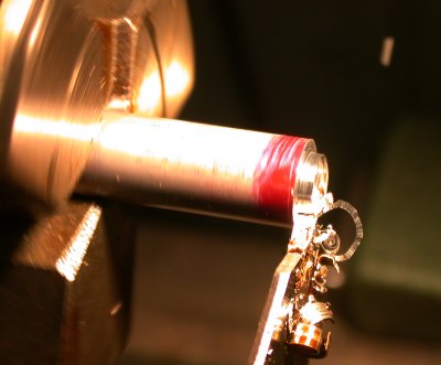 I used
the lathe to trim the elevator autopilot servo control rod to length.
I used
the lathe to trim the elevator autopilot servo control rod to length.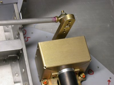 Here
is the elevator autopilot servo, mounted and torqued. The actuating
rod is still temporarily fastened. Just above & below where the
rod crosses over the bulkhead, you can see the 2 solid 470-6 rivets I had to
use, because the holes got so enlarged from trying to drill out the rivets
down in there. The upper one is also going through the upright angle
for the custom baggage compartment. The rest of the rivets you see
going through the bulkhead, along the servo plate flange, are CR3242-5-2
oversized 5/32" CherryMax rivets.
Here
is the elevator autopilot servo, mounted and torqued. The actuating
rod is still temporarily fastened. Just above & below where the
rod crosses over the bulkhead, you can see the 2 solid 470-6 rivets I had to
use, because the holes got so enlarged from trying to drill out the rivets
down in there. The upper one is also going through the upright angle
for the custom baggage compartment. The rest of the rivets you see
going through the bulkhead, along the servo plate flange, are CR3242-5-2
oversized 5/32" CherryMax rivets. 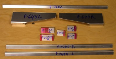 LOTS of
brackets to fabricate for the subframe. These are from DWG 24A.
There were a couple more, not shown here, from DWG 24.
LOTS of
brackets to fabricate for the subframe. These are from DWG 24A.
There were a couple more, not shown here, from DWG 24.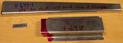 A couple
more pieces to fabricate. The little piece is a shim plate I had to
make from 0.063" because I ended up with the F643-1 cut 1/16" too
short. I later found out the F697 is cut wrong, so don't cut yours
like this.
A couple
more pieces to fabricate. The little piece is a shim plate I had to
make from 0.063" because I ended up with the F643-1 cut 1/16" too
short. I later found out the F697 is cut wrong, so don't cut yours
like this.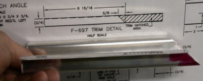 Here's
the F697 I cut, and the drawing it's based on. It sure seems to me that
the dotted line represents the legs, and they don't provide an end view, so I
made it like this. I later figured out, from looking at the iso
drawing and seeing where the F697 was going to mount, that it's wrong.
The legs are DOWN when the cut is made. I suggested to Van's that they
clarify the drawing, but the guy I was talking to at the time said I should
been able to figure it out by also looking at the isometric drawing.
Here's
the F697 I cut, and the drawing it's based on. It sure seems to me that
the dotted line represents the legs, and they don't provide an end view, so I
made it like this. I later figured out, from looking at the iso
drawing and seeing where the F697 was going to mount, that it's wrong.
The legs are DOWN when the cut is made. I suggested to Van's that they
clarify the drawing, but the guy I was talking to at the time said I should
been able to figure it out by also looking at the isometric drawing.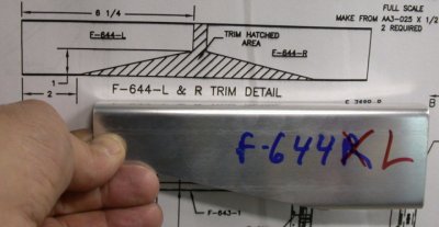 They also
don't provide an end view for the F644, so I interpreted that wrong,
too. But it didn't matter, as I just switched LT & RT, and then
they matched up.
They also
don't provide an end view for the F644, so I interpreted that wrong,
too. But it didn't matter, as I just switched LT & RT, and then
they matched up. This shows
how the F643 end had to be recut, using the CORRECT side as the 90 degree
angle, because it's a wedge shape.
This shows
how the F643 end had to be recut, using the CORRECT side as the 90 degree
angle, because it's a wedge shape.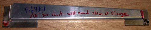 This pic shows
the F643 cut properly - with the 90 degree cuts at both ends on the SAME
SIDE. I had initially made my 90 cut (on RT in this pic) at 90 degrees
with the top flange in this pic. That flange is not 90 degrees at the
other end (LT in this pic), so it lost me 1/16", which I had to make up
by using the shim you see super-glued on to the LT end flange in this pic.
This pic shows
the F643 cut properly - with the 90 degree cuts at both ends on the SAME
SIDE. I had initially made my 90 cut (on RT in this pic) at 90 degrees
with the top flange in this pic. That flange is not 90 degrees at the
other end (LT in this pic), so it lost me 1/16", which I had to make up
by using the shim you see super-glued on to the LT end flange in this pic.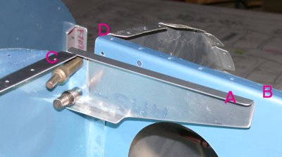 Here is the LT
F644 clecoed in place. As you can see here, the upper one has been
enlarged to 3/16" and the bottom one is 5/32", due to having a
hard time getting it clamped properly and aligned both with the tops of the
center subpanel (C) and outboard subpanel (D), as well as being at the right
angle so the top of it (A) is flush with the top of the F745 (B).
Here is the LT
F644 clecoed in place. As you can see here, the upper one has been
enlarged to 3/16" and the bottom one is 5/32", due to having a
hard time getting it clamped properly and aligned both with the tops of the
center subpanel (C) and outboard subpanel (D), as well as being at the right
angle so the top of it (A) is flush with the top of the F745 (B).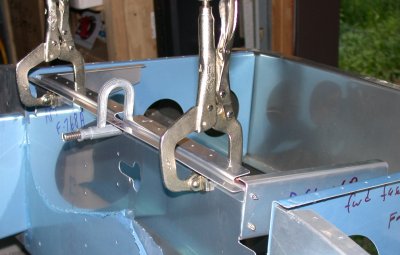 Here is the
F768C, center seal support, clamped into place against the F768A, center
subpanel.
Here is the
F768C, center seal support, clamped into place against the F768A, center
subpanel. Here are the F768D
outboard seal supports, cut and ready to match to the outline of the F768B
outboard subpanels.
Here are the F768D
outboard seal supports, cut and ready to match to the outline of the F768B
outboard subpanels.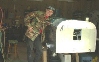 The DAR
at the Lawrence, MA fly-in suggested I include pics showing ME with the
plane occasionally, just to prove it's really me working on this
plane. Yep, that does appear to be me, all right, just stopping in to
observe what my plane building slaves have accomplished so far ;-)
The DAR
at the Lawrence, MA fly-in suggested I include pics showing ME with the
plane occasionally, just to prove it's really me working on this
plane. Yep, that does appear to be me, all right, just stopping in to
observe what my plane building slaves have accomplished so far ;-)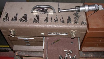 I
went through my drawer of threaded drill bits and sorted them out, so it
doesn't take 15 minutes every time I need to find a specific diameter and length
bit. I left 'em here, cuz I haven't yet figured out a good mechanism
to keep them stored sorted.
I
went through my drawer of threaded drill bits and sorted them out, so it
doesn't take 15 minutes every time I need to find a specific diameter and length
bit. I left 'em here, cuz I haven't yet figured out a good mechanism
to keep them stored sorted. I made this
little 1/8" thick gage from 2 pieces of 0.063" scrap superglued
together, to easily gage when the tops of the seal supports are the correct
1/8" below the subpanel top flange.
I made this
little 1/8" thick gage from 2 pieces of 0.063" scrap superglued
together, to easily gage when the tops of the seal supports are the correct
1/8" below the subpanel top flange. Here is one
end of the F703B, after all the bending cuts have been made and I'm starting
to bend it to match the contour of the top of the instrument panel.
Here is one
end of the F703B, after all the bending cuts have been made and I'm starting
to bend it to match the contour of the top of the instrument panel.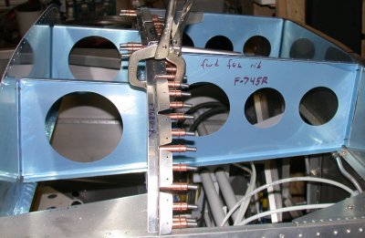 Here are the 3
seal supports after being bent to match the contour of the tops of the
subpanel, and drilled and clecoed into place.
Here are the 3
seal supports after being bent to match the contour of the tops of the
subpanel, and drilled and clecoed into place.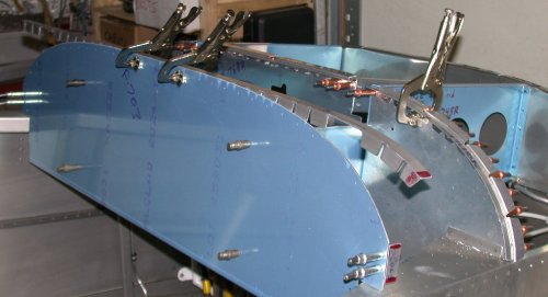 Here, I am
just starting to clamp the F703B to the top of the instrument panel, working
my way out from the center, and bending the F703B as I go, to match the
contour of the instrument panel. In the center foreground, you see the
RT F703C angle clecoed in place.
Here, I am
just starting to clamp the F703B to the top of the instrument panel, working
my way out from the center, and bending the F703B as I go, to match the
contour of the instrument panel. In the center foreground, you see the
RT F703C angle clecoed in place.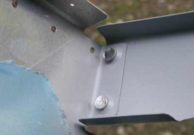 This shows
the two 426-6 rivets I had to use on the LT F644, because I'd had to enlarge
my initial holes some, to get the F644 positioned correctly. I guess
these oughta hold it!
This shows
the two 426-6 rivets I had to use on the LT F644, because I'd had to enlarge
my initial holes some, to get the F644 positioned correctly. I guess
these oughta hold it!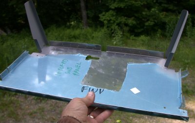 Here's
the F786A center subpanel, with the two F644s riveted on.
Here's
the F786A center subpanel, with the two F644s riveted on.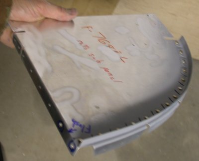 and here is one of the 2 outboard subpanel assemblies, with the seal support
riveted on
and here is one of the 2 outboard subpanel assemblies, with the seal support
riveted on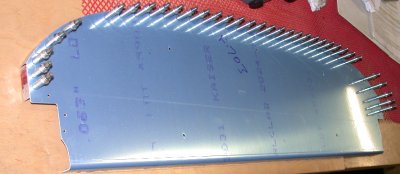 Here is the
F703 instrument panel, with the F703B and F703C support angles clecoed on.
Here is the
F703 instrument panel, with the F703B and F703C support angles clecoed on. This
partially shows the layout for the F793 brackets. The drawing for this
didn't give dimensions for where to center the 1 7/16" arc cut, but the
drawing was full scale, fortunately, so I measured it directly on the
print. I came up with 1 49/64" from each rivet hole. So, I
clamped the F793 to the bench and used the dividers to lay it out.
This
partially shows the layout for the F793 brackets. The drawing for this
didn't give dimensions for where to center the 1 7/16" arc cut, but the
drawing was full scale, fortunately, so I measured it directly on the
print. I came up with 1 49/64" from each rivet hole. So, I
clamped the F793 to the bench and used the dividers to lay it out.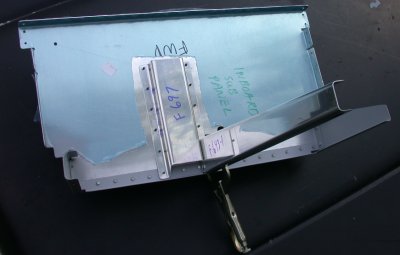 Here
are the new F697 (correctly cut this time) and the F643-1 clecoed onto the
growing center subpanel assy. I still don't understand why that F697
is shaped that way. I am hoping it will become apparent at some point
here.
Here
are the new F697 (correctly cut this time) and the F643-1 clecoed onto the
growing center subpanel assy. I still don't understand why that F697
is shaped that way. I am hoping it will become apparent at some point
here. 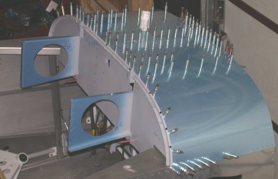 This pic
shows the subpanel completely assembled, and about 3/4 of the way through
clecoing the F771 skin on over it. The top flanges of the F644 and
F643 ribs were marked with center lines, and match drilled to the skin as
part of this. The bottom edge, where the top skin joins the side skin,
sure didn't want to bend down and be clecoed. My wingnut clecoes sure
helped with that. You can barely see one, as the second from the LT on
the bottom here.
This pic
shows the subpanel completely assembled, and about 3/4 of the way through
clecoing the F771 skin on over it. The top flanges of the F644 and
F643 ribs were marked with center lines, and match drilled to the skin as
part of this. The bottom edge, where the top skin joins the side skin,
sure didn't want to bend down and be clecoed. My wingnut clecoes sure
helped with that. You can barely see one, as the second from the LT on
the bottom here. During the summer, I
sometimes get huge moths coming in. This one's wingspan was about
6-8"
During the summer, I
sometimes get huge moths coming in. This one's wingspan was about
6-8"