 Here is my initial layout of how to put the aileron servo in
 WINGS May, 2004
May 20 - Receive BMA autopilot servos. Start looking at layout for wing servo. Figure out where it should go, how it should be mounted, what to use for rods and rod ends, how & where to attach rod ends. 2.5 hr
Here is my initial layout of how to put the aileron servo in
May 24 - clean up workbench. Start planning for rods and rod ends I'll need for the servos, and how the rod ends will attach to the rods. Decided to get M3414M rod ends. They are only 1/4-28 threads, while most are 3/8". They should be strong enough, as that's what Van's uses for the aileron actuating rod ends. Also, they are longer than most of the 3/8" rod ends, with over an inch of threads. That'll give me lots of thread engagement in the tubing. This lets me use tubing as small as 3/8". The 3/8" with 0.083" wall thickness is perfect, with an ID of .209. The next thinner wall, 0.065', would only give me an ID of .245; not enough for thread engagement with the 1/4"-28 rod ends. I put together orders to Van's and ACS for rods, rod ends, 0.063" T2024T3 plates, and other servo hardware I will need. Van's prices for the same rod ends were MUCH less than ACS ($8.44 vs $22.75). I had noticed that big price difference when I ordered ProSeal, too. 2.25 hr
May 25 - more servo layout and parts planning. Placed parts orders with ACS and Van's. I decided to put the servo attach plate against the bottom skin, rather than the top one. It'll be more trouble, but then I can tie into 2 rows of main wing spar rivets without having to drill out any existing spar rivets, and the servo will be sitting on, rather than hanging from, the skin. 4.0 hr
May 27 - Received my order from Van's for 0.063" plate, rod ends, etc. for servo system. Start laying out bends for flanged plate to go between 2 ribs. After much dicking around, making practice bends, and grinding radii into the brake fingers, I took the plunge and made a huge SWAG as to how much setback to allow for the bend, and made the bends for the 2 flanges in one of the 12" x 12" 0.063 plates I just got from Van's. Incredibly, it came out of the brake as a PERFECT slip fit between the 2 ribs. I was amazed at how well it came out, especially considering how wildly I was having to guess at how much setback to use, how much to allow for the rubber hose, etc. Still more pondering about whether to attach servo to top skin or bottom skin. If I use the top, it'll be MUCH easier to install, rig, test, etc initially. If I use the bottom, I won't have to drill out spar rivets, the servo will sit, not hang, and there'll be no screws and extra rivets in my top skin. I eventually decided on using the top skin, for the ease of installing and testing it. I was also pondering whether to make a round access panel in the opposite skin. I decided I could get sufficient access through the rib lightening hole via the bellcrank access panel. I can always add an access panel later if reaching through the lightening hole is too difficult. I also considered using tapered shims, instead of the lower plate, to get the bottom surface flush with both the skin and the top of the wing main spar. I ended up deciding to make lightening holes in the panels after I get the rivet layouts done. I also decided to use the existing rod end attachment bolt on the aileron bellcrank as my rod end attachment point. I removed the existing spacer, and cut it down so I could put a second rod end bearing in there. Then I went back to working on the cabin frame and elevator servo layout. 5.75 hr
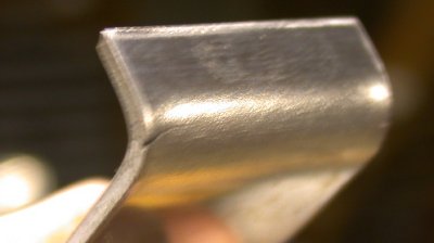 An initial test of bending the 0.063 plates caused cracking. I ground
a radius on the fingers of my brake and added
some rubber hose to the finger edges to
increase the radius. I also realized I was making the test bend parallel to
the grain lines. After adding the hose and bending perpendicular to
the grain lines, I no longer had any cracking. It's nice when things
go right! It was difficult to measure the plate so the flange legs would be
exactly as far apart as the ribs. It came out to a perfect slip fit when I
made the bends on the actual plate, after doing a couple more practice/test
bends like this one.
An initial test of bending the 0.063 plates caused cracking. I ground
a radius on the fingers of my brake and added
some rubber hose to the finger edges to
increase the radius. I also realized I was making the test bend parallel to
the grain lines. After adding the hose and bending perpendicular to
the grain lines, I no longer had any cracking. It's nice when things
go right! It was difficult to measure the plate so the flange legs would be
exactly as far apart as the ribs. It came out to a perfect slip fit when I
made the bends on the actual plate, after doing a couple more practice/test
bends like this one.
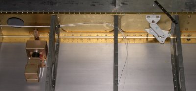
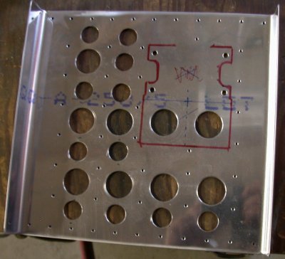
 I eventually decided I could come in 1 bay closer to the aileron bellcrank,
without getting excessive actuating rod angles, so I ended up using the next
bay outboard from the bellcrank to set up the mounting plates, shown here
with the blue coating still on. I also settled on a design that has a
flat plate underneath, to bring the surface up to the level of the
spar. Then I drilled out the fwd row of spar rivets for this
bay. The other plate, with the 2 flanges for fastening to the 2 ribs,
goes on top of that. So, the main plate will be fastened to the spar,
2 ribs, the bottom plate, and the skin, plus the flanges add a lot of stiffening. I will
also flange the fwd end (LT in this pic) of the bottom plate, for even more
stiffening between the spars. The servo will then be bolted to the 2
plates, through the wing skin, and the actuating rod will go through the rib
lightening hole, and the rod end will use the same bolt as the main aileron
actuating rod coming in from the control stick. The wing is upside
down in this pic here. There were advantages and disadvantages to using the top
skin versus the bottom skin, but I ended up deciding it would be
too difficult to position things if I was trying to work under that last
remaining bottom skin, so I decided to use the top skin.
I eventually decided I could come in 1 bay closer to the aileron bellcrank,
without getting excessive actuating rod angles, so I ended up using the next
bay outboard from the bellcrank to set up the mounting plates, shown here
with the blue coating still on. I also settled on a design that has a
flat plate underneath, to bring the surface up to the level of the
spar. Then I drilled out the fwd row of spar rivets for this
bay. The other plate, with the 2 flanges for fastening to the 2 ribs,
goes on top of that. So, the main plate will be fastened to the spar,
2 ribs, the bottom plate, and the skin, plus the flanges add a lot of stiffening. I will
also flange the fwd end (LT in this pic) of the bottom plate, for even more
stiffening between the spars. The servo will then be bolted to the 2
plates, through the wing skin, and the actuating rod will go through the rib
lightening hole, and the rod end will use the same bolt as the main aileron
actuating rod coming in from the control stick. The wing is upside
down in this pic here. There were advantages and disadvantages to using the top
skin versus the bottom skin, but I ended up deciding it would be
too difficult to position things if I was trying to work under that last
remaining bottom skin, so I decided to use the top skin.
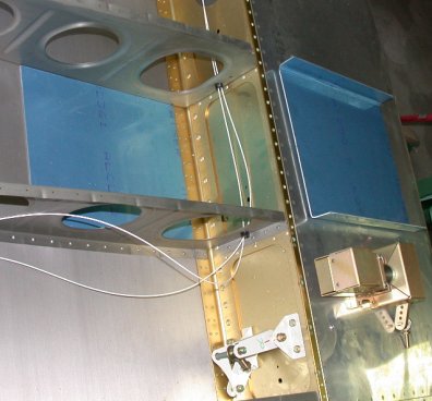
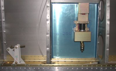
 Here are the 2 plates in place, with the servo positioned on top of them.
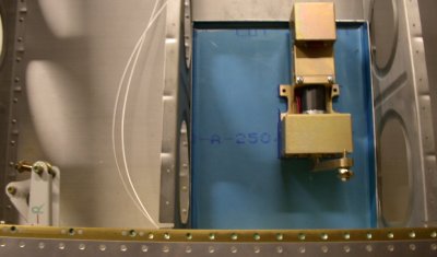
 In trying to determine which hole on the servo arm I should use, I set up
this test to measure the travel between centered and 45 degrees (the point
at which vertical travel starts being greater than horizontal travel.).
In trying to determine which hole on the servo arm I should use, I set up
this test to measure the travel between centered and 45 degrees (the point
at which vertical travel starts being greater than horizontal travel.).
 Setting up the layout to determine the rod length to use
May 28 - Received ACS order #1, with my 3/8" extra heavy wall servo actuating rods. Placed another order to Van's for yet more parts. The short aileron rod will be fine. I may need to go to a bit bigger rod for the longer elevator actuating rod. Drilled and threaded rods for rod end bearings. Started putting together yet more orders for parts. Started making servo rods. The rod end bearing thread fit seemed a bit sloppy after I'd drilled and tapped the rods, but I got the same results when I did it on the metal lathe, so I think it's OK. There's about a full inch of engaged threads; that's one reason I chose these particular rod ends - they're only 1/4"-28 (so I can use smaller rod), and the threads are longer than other rod end bearings. I'll use plenty of Loc-Tite when I do the final assembly. 4.0 hr
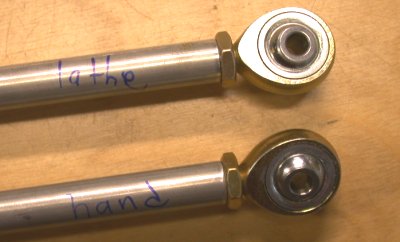 I tried drilling and threading a couple pieces of aluminum tubing, to make
the servo actuating rods. I did one by hand, and the other with the
lathe. Both had the same amount of play in the threads.
I tried drilling and threading a couple pieces of aluminum tubing, to make
the servo actuating rods. I did one by hand, and the other with the
lathe. Both had the same amount of play in the threads.
May 29 - Got really into it and pulled an all-nighter working on the servo stuff. Lay out aileron servo rods, cut to length, drill & tap both ends, attach rod ends. Added a stiffening flange to bottom mount plate. Measured & trimmed servo mount plates. Drilled out 11 spar rivets for servo mount plate. Laid out & drilled plate attachment rivets. Drilled & clecoed plates to skin & ribs. Deburred plates. Laid out lightening holes in plates. Cut & deburred lightening holes. Countersunk skin dimple holes in bottom plate. Drilled & cut out even more lightening holes, especially in bottom plate. I was trying to decide between using 3/32" rivets on the plate flanges or using 1/8". I eventually decided 1/8" was the best bet, so I laid out the rivet holes on plate flanges, and drilled and clecoed them in. Then I cleaned the plates and started prepping them for primer. 13.75 hr
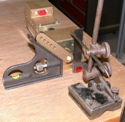
 Laying out the rod, with a rod end bearing on one end, to get the rod
length. The 90 degree square on the servo arm shows me where the servo
arm wants to be when the aileron bellcrank is in the neutral position, and
the 45 degree angle shows me all the travel I want the arm to make.
After 45 degrees of travel, there is more down movement than horizontal.
Laying out the rod, with a rod end bearing on one end, to get the rod
length. The 90 degree square on the servo arm shows me where the servo
arm wants to be when the aileron bellcrank is in the neutral position, and
the 45 degree angle shows me all the travel I want the arm to make.
After 45 degrees of travel, there is more down movement than horizontal.
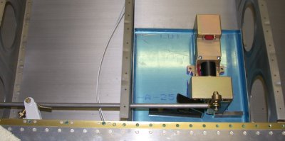
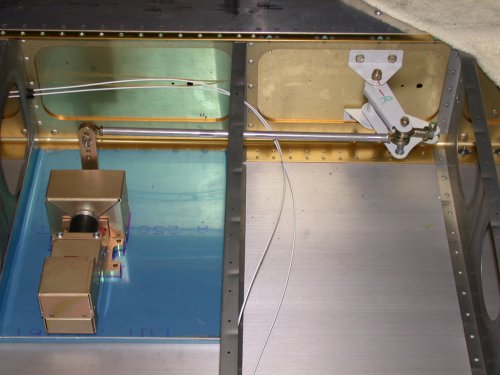 This is with the actuating rod cut to length and both rod ends
attached. The servo is just sitting there for now, marked as to
position.
This is with the actuating rod cut to length and both rod ends
attached. The servo is just sitting there for now, marked as to
position.
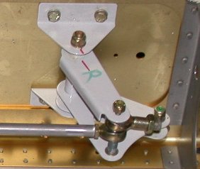 This shows where I shortened the main aileron control rod attachment
bushing, so I could get both rod ends onto the same bellcrank bolt.
The main aileron control rod, from the stick, attaches to the rod end on the
RT in this pic. The red line shows neutral position on the bellcrank.
This shows where I shortened the main aileron control rod attachment
bushing, so I could get both rod ends onto the same bellcrank bolt.
The main aileron control rod, from the stick, attaches to the rod end on the
RT in this pic. The red line shows neutral position on the bellcrank.
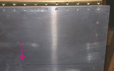
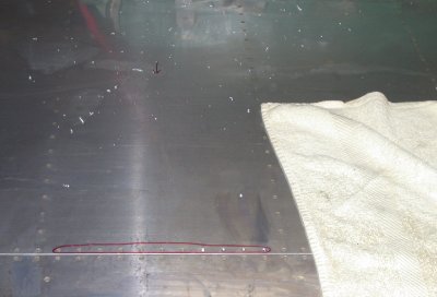 Drilling out one row of the wing spar rivets. The arrow at the top of
the pic makes sure I am doing this in the RIGHT BAY!
Drilling out one row of the wing spar rivets. The arrow at the top of
the pic makes sure I am doing this in the RIGHT BAY!
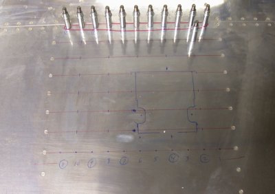 Laying out the rivet hole pattern on the skin
 This
is the top plate, after drilling all the rivet holes and lightening holes,
and deburring & cleanup.
This
is the top plate, after drilling all the rivet holes and lightening holes,
and deburring & cleanup.
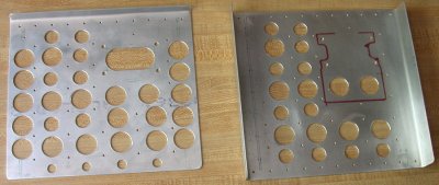 This shows both the top plate and bottom plate, done and ready for primer.
May 30 - Work with Karla on dimpling the skin rivet holes. We tried using the shaft from the C-frame holding the male die and the female die in a heavy bucking bar, but it was too difficult to get the alignment perfectly square, so we were making marks on the skin. I switched over to the Avery Pop rivet dimpler, with Karla helping from the other side, and that worked fine. I countersunk the plates for four #10 screws, then washed and primed them. I started using a new method of primer preparation that I think works better. I wash them in my shop sink, with hot water and dish soap. It seems to get all that crud from Scotch-Brite-ing them off more thoroughly than using the SEM solve I've been using. I also made a new holder for all my countersink cages. While the plate primer hardened, I started working on laying out the AOA ports on the RT wing. I made a test plate to see how well the screws would fit into dimples. The screws supplied with the AOA kit are apparently some friggin hardware store stuff, with heads less than 90 degrees, rather than the proper (to fit the standard 100 degree dimples) MS screws. What the hell are those people thinking of?? So, I had to make up yet another order to ACS (been averaging about an order a day all week) to get the proper MS screws with 100 degree heads. I also ordered a #4 dimple die from Cleaveland. I went back to the servo plates, and clecoed them in place. Karla and I did some rivet gun practice for awhile, then we drove the solid rivets through the skin and the 2 plates. It went well; Karla did a good job on the gun. I tried to do the plate flange rivets in solid rivets, but there turned out to be no way I was going to get a squeezer or a gun in there, so I decided to do them in CR3213-4-3 CherryMax rivets. I only had 6, so I added more of them to my growing order list from ACS. I cleaned up the big mess everywhere, then started mounting the aileron servo to the plates. Two of the mount holes in the servo were too close to the edge of the servo frame, so I had to grind flats on 2 of the washers. I moved the rod end down 2 holes on the servo arm, because I now understand that the arm needs to be perpendicular to the actuating rod, rather than to the plates, when the bellcrank is in the neutral position. That also give me more nearly 45 degrees of servo arm travel, as specified in the BMA servo manual. Another good, long, productive day. 10.25 hr
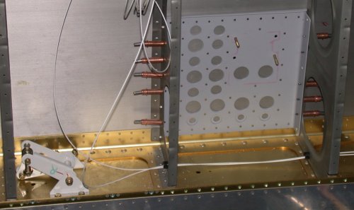 Here are the 2 plates, clecoed into place, and ready to rivet.
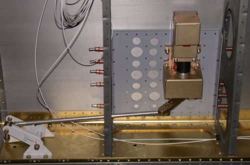 Here are the plates riveted in place, the servo mounted, and the rod
installed. I'm just waiting for more CherryMax rivets to finish
riveting the flanges to the ribs.
Here are the plates riveted in place, the servo mounted, and the rod
installed. I'm just waiting for more CherryMax rivets to finish
riveting the flanges to the ribs.
 This is the layout for one of the 2 AOA probes.
GO TO JUNE WINGS
BACK TO MY RV BUILDER'S HOME
BACK TO BRIAN'S HOME