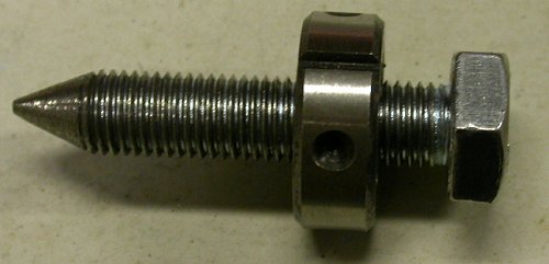
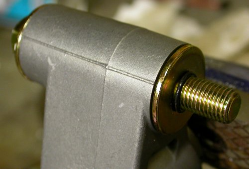
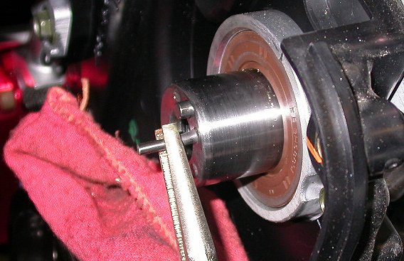
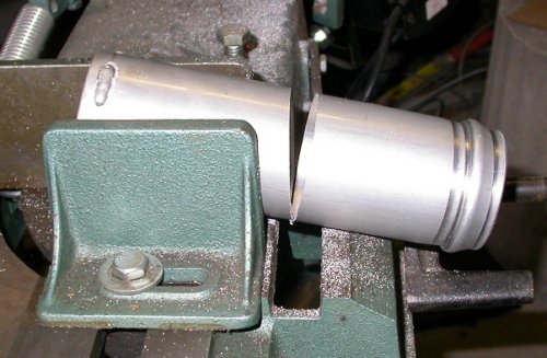
 Grinding the tip of a 10-1.25 x 50mm bolt to use as a flywheel stop/lock.
Put the die on first, then grind it. Then, as you remove the die, it
will clean the threads. It is very difficult to get the die on after
you grind the threads.
Grinding the tip of a 10-1.25 x 50mm bolt to use as a flywheel stop/lock.
Put the die on first, then grind it. Then, as you remove the die, it
will clean the threads. It is very difficult to get the die on after
you grind the threads.ENGINE WORK December, 2005
Dec 2 - Trying to get changes Jan made to his web site & the Install Manual straightened out. Help other STi users & get them a PDF of the STi Upgrade chapter until I get the manual straightened out. Start removing cam covers. The RT has 4 bolts (10mm head) and the LT has 3 bolts. The center cover comes out last, and it has 8 bolts; 7 stepped and one non-stepped that goes in the lower LT corner. The center cover takes a bit of gentle prying to get it loose. Be careful of the rubber gasket. Rotate engine until the double hash marks on the sprockets (painted green) are aligned with each other on each side. Printed out the STi Upgrade Manual and emailed Robert and the STi list some questions about all this. Clean out threaded flywheel stop hole, and make up flywheel stop bolt. The STi upgrade manual called for a 10-1.25 x 100mm bolt, but I had a 50mm bolt available and that worked fine. Removed oil covers from upper sprockets. With sprockets locked in place to the crank by the belt, and the crank locked in place by the flywheel stop bolt, cracked the sprocket mount bolts loose 1/2 turn, so I can easily remove them after the belt is removed. Removed "A" idler first, then the cam belt tensioner. When I took the belt off the RT sprockets, they rotated about 1/4 turn. The upper (intake) went CCW and the lower (exhaust) went CW. Put new sprockets on and replaced bolts with shorter ones supplied. Spent a long time slowly squeezing the tensioner actuator rod in the vise. The manual said to use a press, but that's one of the few tools I still do not have. Be sure to insert the tensioner holding pin from the ROLLER side; otherwise, you'll be unable to reinstall the tensioner. After finally getting the tensioner rod compressed and held down with a small Allen wrench, I reinstalled the tensioner and torqued it and the belt idler roller "A" bolt to 29 ft lb. Worked awhile on fitting the supercharger bracket. 6.0 hr + 0.5 hr doc
Grinding the tip of a 10-1.25 x 50mm bolt to use as a flywheel stop/lock.
Put the die on first, then grind it. Then, as you remove the die, it
will clean the threads. It is very difficult to get the die on after
you grind the threads.
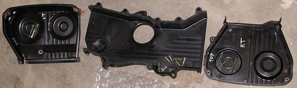 Here are the 3 cam belt covers removed, with their hardware.
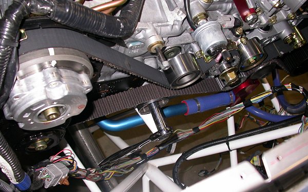
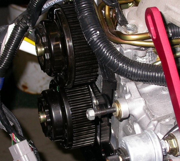
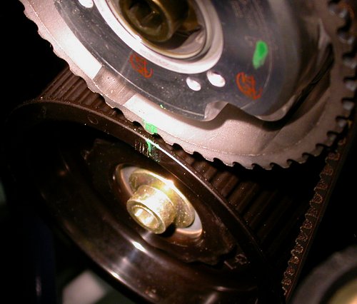 Align the double hash marks (marked in green) on the upper and lower
sprockets with each other.
Align the double hash marks (marked in green) on the upper and lower
sprockets with each other.
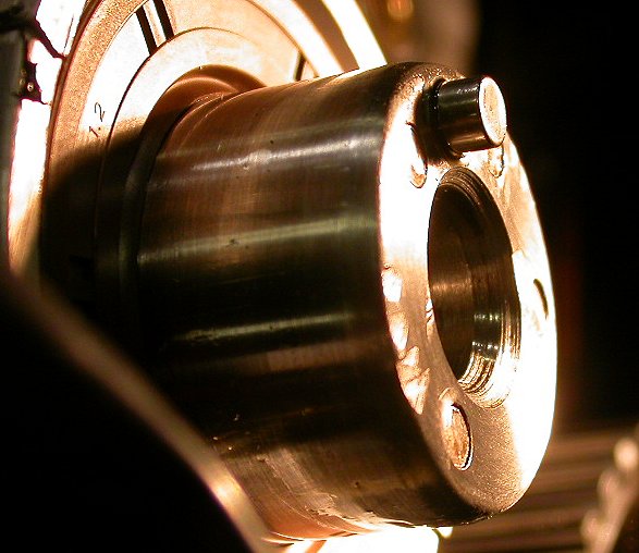
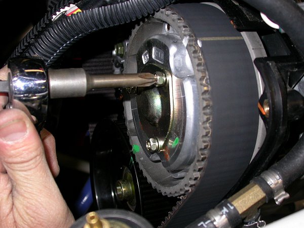 Remove the o-ringed covers to expose the big Allen bolts holding the
sprockets on. Because I am doing all this work with the engine mounted
to the firewall, everything is close work, and not much room to maneuver or
get a screwdriver in there.
Remove the o-ringed covers to expose the big Allen bolts holding the
sprockets on. Because I am doing all this work with the engine mounted
to the firewall, everything is close work, and not much room to maneuver or
get a screwdriver in there.
 With the flywheel locked and the belt holding the sprockets locked to the
crankshaft, just crack those bolts loose with a 10mm Allen wrench. I
needed about a 15" persuader on the LT side.
With the flywheel locked and the belt holding the sprockets locked to the
crankshaft, just crack those bolts loose with a 10mm Allen wrench. I
needed about a 15" persuader on the LT side.
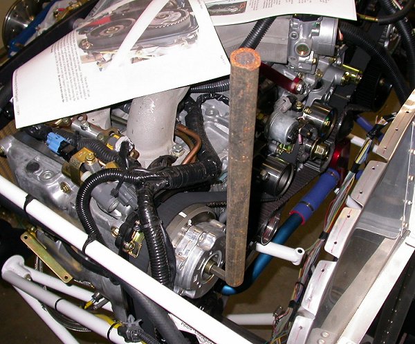
 The RT side was a bit tougher, and this 3/4" pipe 3-4 feet long got the job done. Those
sprocket bolts are TIGHT! Once the sprocket bolts are cracked loose
1/2 turn, then proceed with removing the belt idler, tensioner, and the
belt, then remove the sprocket bolts and the sprockets.
The RT side was a bit tougher, and this 3/4" pipe 3-4 feet long got the job done. Those
sprocket bolts are TIGHT! Once the sprocket bolts are cracked loose
1/2 turn, then proceed with removing the belt idler, tensioner, and the
belt, then remove the sprocket bolts and the sprockets.
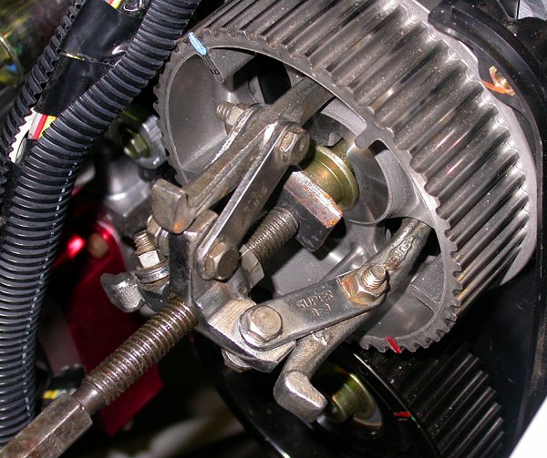
 I found it easier and better to remove the belt idler "A" (as per the Subaru
manual) prior to removing the tensioner. That's the
ratchet & socket in the middle of the pic. The manual says this roller
has less side tension on the bolt, and thus less likely to stress the
threads as the bolt is removed.
I found it easier and better to remove the belt idler "A" (as per the Subaru
manual) prior to removing the tensioner. That's the
ratchet & socket in the middle of the pic. The manual says this roller
has less side tension on the bolt, and thus less likely to stress the
threads as the bolt is removed.
 This is the tensioner. Don't forget the little o-ring on the threads.
It may fall off when you take the tensioner off, so don't forget it or lose
it.
This is the tensioner. Don't forget the little o-ring on the threads.
It may fall off when you take the tensioner off, so don't forget it or lose
it.
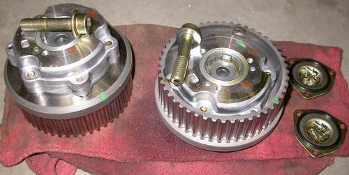 Here are the removed sprockets and hardware.
 The
sprockets are marked for what goes where. The plastic one is for the
RT (LT for us) intake. The other sprocket (steel) says LT INTAKE.
The
sprockets are marked for what goes where. The plastic one is for the
RT (LT for us) intake. The other sprocket (steel) says LT INTAKE.
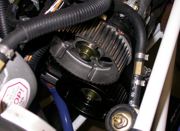
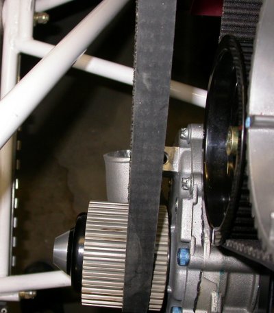
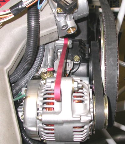
 Here is the new LT intake (upper) sprocket installed. The alternator
is removed in this pic. It mounts to the stud with the nut, and its
belt tension is set by adjusting its position on the red anodized bar.
Here is the new LT intake (upper) sprocket installed. The alternator
is removed in this pic. It mounts to the stud with the nut, and its
belt tension is set by adjusting its position on the red anodized bar.
 Here is the new RT intake sprocket installed. This was before I found
out by accident that we need to put pins into the oil galleries going to the
old sprockets, so the sprockets had to come off again. NO INSTRUCTIONS
at all with any of this.
Here is the new RT intake sprocket installed. This was before I found
out by accident that we need to put pins into the oil galleries going to the
old sprockets, so the sprockets had to come off again. NO INSTRUCTIONS
at all with any of this.
Dec 3 - After exchanging some emails with the STi group, found out I need to put those little pins, that came in an unmarked bag, into the 4 oil gallery passages in each sprocket shaft. So, I pulled the sprockets off again. They also said I'd need to swap out the oil seals with the ones provided. The pins taper from 0.151" to 0.163". They slide into the holes to about the 0.160" line. Should they be hammered in the rest of the way to flush? I don't know, but I assume so. The new seals are about 1/2" smaller ID, so that's obviously why they were included in the kit. I deburred the cut ends of the 8 pins and put them into the holes, waiting for Jan's confirmation before hammering them in. Spent some time researching how to remove & replace the oil seals, but I can't find anything about it in the Subaru manual. I tried tapping in one of the tapered plugs. They sure go in pretty TIGHT. I ended up popping the oil seals out OK with a long Phillips screwdriver. On the RT side, I had to use the notch in the top of the plastic cover to get clearance for the screwdriver. I oiled the lip of the seal before sliding it over the shaft. I got sick of waiting to hear from Jan on the oilplugs, so I drove them home. It's a good idea to chamfer the cut ends. If they were about 1/8" shorter, they'd be a lot better. I made & used a short drift pin to drive them the last 1/8" or so, and make sure I seated them below the shaft surface. After all the hammering, I found that the sprockets would no longer slip on over the shaft. Apparently, the pins forced into the holes so tight caused the shaft to swell a bit. I finally got one started, and used the bolt to draw the sprocket in tight to the shaft. The LT one was tight, the RT one was even tighter. Then resumed working on the supercharger mount bracket. The bracket bolt hole alignment is good at first, but then as the angled bolt tightens, it pulls everything over and causes the other 2 bolts to lose alignment. I later decided to mill one of the holes a bit elongated, so the bolt would go in smoothly, without jamming against the bracket. From looking at all this, it looks like later routine timing belt replacements will be a bitch, once the supercharger and intercooler and all related parts are installed. 4.25 hours
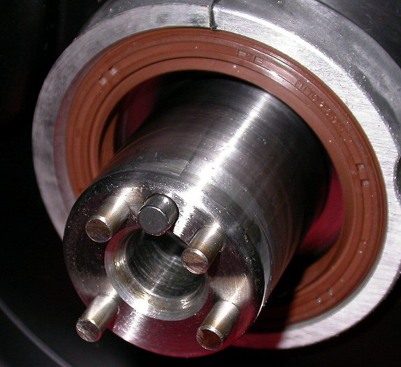 This pic shows the old seal, with an ID about 1/2" bigger than the shaft and
the new seal. It has to be replaced. You can also see the
4 oil line plugs I installed. They are pressed in finger tight,
and they are sticking out about 3/8" to 1/2". Since Jan didn't
provide any sort of instructions with any of this, I drove them in as is.
I then decided to recommend to others that they cut 1/16" to 1/8" off the
end of these tapered plugs before driving them in, as they went in too hard
for me. I later found out Jan recommended cutting them down so they
stick out 1/8" to 1/4".
This pic shows the old seal, with an ID about 1/2" bigger than the shaft and
the new seal. It has to be replaced. You can also see the
4 oil line plugs I installed. They are pressed in finger tight,
and they are sticking out about 3/8" to 1/2". Since Jan didn't
provide any sort of instructions with any of this, I drove them in as is.
I then decided to recommend to others that they cut 1/16" to 1/8" off the
end of these tapered plugs before driving them in, as they went in too hard
for me. I later found out Jan recommended cutting them down so they
stick out 1/8" to 1/4".
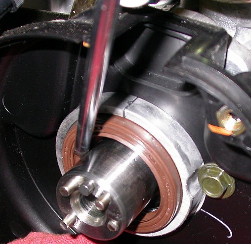 Pop out the old seal. A long blade SnapOn Phillips screwdriver
worked well for me. Small enough to get in there behind the
seal, big enough to not bend. Note that I am aligning the screwdriver
so the screwdriver can use the slot in the cover backing plate as the seal
gets popped out.
Pop out the old seal. A long blade SnapOn Phillips screwdriver
worked well for me. Small enough to get in there behind the
seal, big enough to not bend. Note that I am aligning the screwdriver
so the screwdriver can use the slot in the cover backing plate as the seal
gets popped out.
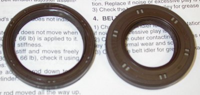 This pic shows why we have to replace the oil seal - big difference in ID.
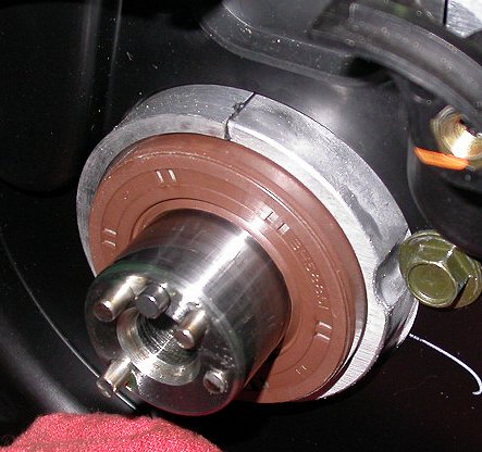 Here is the RT oil seal, ready to be driven in. You can also see here
that I have driven one of the oil plugs nearly all the way in. It's sticking
out about 1/16", and is already so tight it's starting to peen over.
That last 1/16" or so went in really HARD. Don't do yours this
way. Grind the length of the plugs so they stick out no more
than 1/4" when you put them in finger tight.
Here is the RT oil seal, ready to be driven in. You can also see here
that I have driven one of the oil plugs nearly all the way in. It's sticking
out about 1/16", and is already so tight it's starting to peen over.
That last 1/16" or so went in really HARD. Don't do yours this
way. Grind the length of the plugs so they stick out no more
than 1/4" when you put them in finger tight.
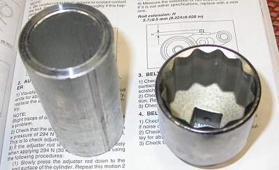 Use something to drive the new seal in. A 1 3/4" socket works well, or
a piece of heavy wall tubing.
Use something to drive the new seal in. A 1 3/4" socket works well, or
a piece of heavy wall tubing.
 Here I am using a cut-off 1/8" drill bit as a punch to drive those pins in
the rest of the way. With the engine mounted to the firewall,
there is not a lot of room to work in here, so I needed something really
short. I only had a few inches in which to swing a hammer. You
can see how the drill bit has bent & mushroomed some, from the effort to
drive those pins all the way in.
Here I am using a cut-off 1/8" drill bit as a punch to drive those pins in
the rest of the way. With the engine mounted to the firewall,
there is not a lot of room to work in here, so I needed something really
short. I only had a few inches in which to swing a hammer. You
can see how the drill bit has bent & mushroomed some, from the effort to
drive those pins all the way in.
 As you can see in this pic, it's important to drive those pins in so they are below
the surface. It also shows how I dinged up the soft end of the shaft a
bit, trying to hammer the pins in to flush, before I realized I was going to
need a drift pin to get them all the way in and below the surface. The
pins got driven in so hard they swelled the shaft a bit, causing the
sprocket fit to go from a snug slip fit to a light press fit. I
was able to barely get the new sprockets started onto the shaft after this,
then I used the attach bolts to draw them onto the shaft. Imagine my
anger when I found out later that, because I got NO instructions with
any of this, that I'd have to pull the sprockets OFF again, because they go
on in a special custom way, not in the they way you'd otherwise think; same
orientation as the ones they replace. I don't know now how I'm going
to get those sprockets off, as they are on TIGHT now.
As you can see in this pic, it's important to drive those pins in so they are below
the surface. It also shows how I dinged up the soft end of the shaft a
bit, trying to hammer the pins in to flush, before I realized I was going to
need a drift pin to get them all the way in and below the surface. The
pins got driven in so hard they swelled the shaft a bit, causing the
sprocket fit to go from a snug slip fit to a light press fit. I
was able to barely get the new sprockets started onto the shaft after this,
then I used the attach bolts to draw them onto the shaft. Imagine my
anger when I found out later that, because I got NO instructions with
any of this, that I'd have to pull the sprockets OFF again, because they go
on in a special custom way, not in the they way you'd otherwise think; same
orientation as the ones they replace. I don't know now how I'm going
to get those sprockets off, as they are on TIGHT now.
 I used the mill to elongate this hole a bit in the direction of the silver
line, so the bolt would go in and line up properly with the threaded holes
in the block.
I used the mill to elongate this hole a bit in the direction of the silver
line, so the bolt would go in and line up properly with the threaded holes
in the block.
Dec 4 - Installed the supercharger mount bracket. I found it's best to get the angled 10mm bolt and the 6mm bolt run in with my fingers, then do the strut bolt. I temporarily installed the supercharger, to see how it'll fit. Randy, from the STi group, is saying the supercharger doesn't fit well on a 7A. I could see that, even with the timing cover off, I have no more than 1/16" of clearance between the supercharger and the frame. Temporarily reinstalled the intercooler, and marked on the intake tube where it interferes with the frame. There's about 7/8" of overlap there. Reamed supercharger mount bracket supercharger mount bolt hole to 5/16". It was already 5/16", but it was just a little cruddy/imperfect inside, so the bolt was kind of a "hammer in" fit. After the reaming, it's a nice snug fit by hand. Wasted a bunch of time swapping out the rubber fuel line going to the fuel rail. I had thought there was no flare in the tube, so I was nervous about having only one clamp holding the hose on. After pulling the hose off, with much difficulty, I found that it already had a flare in it, and was thus OK. It was even more difficult to slide the new hose back on. The old one was so tight, I had to cut it off. Oh well..... While temporarily halted on the engine work, I decided to install the Gary Newsted Low Coolant Level Sensor. Removed the reservoir, drilled it, cleaned it thoroughly, and installed the sensor. Started fabricating a spanner wrench to turn and hold the upper RT sprocket for the belt replacement process. 6.0 hr
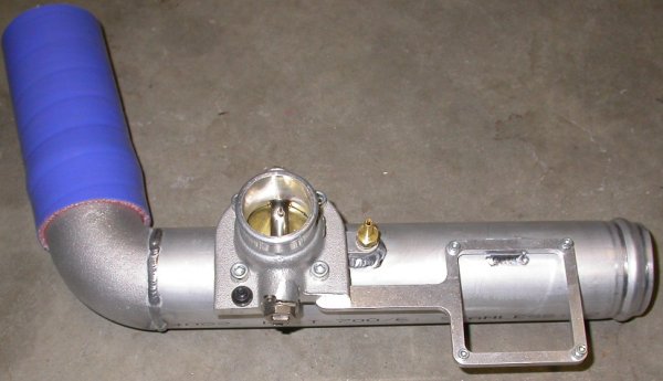
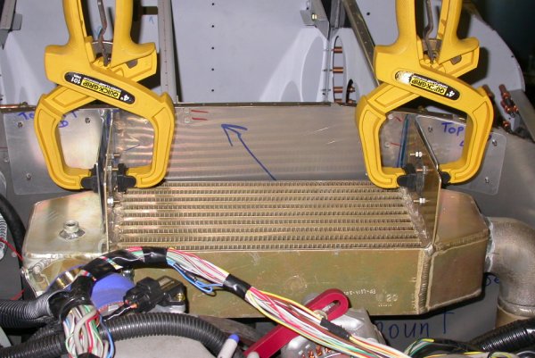
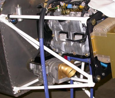
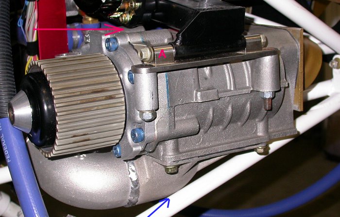 I temporarily mounted the supercharger. With the cam belt cover still
off, there is only about 1/16" clearance between the supercharger and the
cam belt cover backing plate above (red arrow) or the engine frame below
(blue arrow). With the pivot point at "A", and the SC resting on
the frame at the blue arrow, there is only 1/16" clearance at the red arrow.
That'll probably be 0" or less once the cam belt cover is put back on.
Another user has complained about his SC fit on a 7A, and says it isn't
going to work. I've already been complaining about the poor fit
between my intercooler and the 7A frame. It appears that Jan set this
up to fit a RV-7 like Robert's, but the fit isn't looking too good so far on
the 7As.
I temporarily mounted the supercharger. With the cam belt cover still
off, there is only about 1/16" clearance between the supercharger and the
cam belt cover backing plate above (red arrow) or the engine frame below
(blue arrow). With the pivot point at "A", and the SC resting on
the frame at the blue arrow, there is only 1/16" clearance at the red arrow.
That'll probably be 0" or less once the cam belt cover is put back on.
Another user has complained about his SC fit on a 7A, and says it isn't
going to work. I've already been complaining about the poor fit
between my intercooler and the 7A frame. It appears that Jan set this
up to fit a RV-7 like Robert's, but the fit isn't looking too good so far on
the 7As.
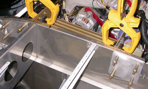
 The blue line here is where the engine frame
diagonal interferes with the intake tube of the intercooler. The line
marks the edge of the frame diagonal tubing. The bottom of the tube
has to go fwd 7/8" to clear the frame tubing.
The blue line here is where the engine frame
diagonal interferes with the intake tube of the intercooler. The line
marks the edge of the frame diagonal tubing. The bottom of the tube
has to go fwd 7/8" to clear the frame tubing.
 Here is the low coolant level sensor, installed in the coolant tank.
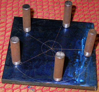 I started laying out plans & parts to make a spanner wrench to hold the
upper sprocket. A later email from Chuck on the STi list made me
realize I can just use the sprocket BOLTS to turn the sprockets.
The upper one, that's loose now, needs to turn in the tightening direction,
so that's OK. The lower one needs to go CCW, but it's on so
tight, it isn't going to budge from turning the cam. So, I won't need
this tool. Only remaining step was to weld the pegs onto the
plate, and weld an old socket (for 3/8" ratchet drive) onto the back.
Oh well.
I started laying out plans & parts to make a spanner wrench to hold the
upper sprocket. A later email from Chuck on the STi list made me
realize I can just use the sprocket BOLTS to turn the sprockets.
The upper one, that's loose now, needs to turn in the tightening direction,
so that's OK. The lower one needs to go CCW, but it's on so
tight, it isn't going to budge from turning the cam. So, I won't need
this tool. Only remaining step was to weld the pegs onto the
plate, and weld an old socket (for 3/8" ratchet drive) onto the back.
Oh well.
Dec 5 - spent lots of time on emails with other STi customers. Finally got some info from Robert Paisley. I am screwed. Because I got no instructions with any of these parts, and several parts have tricky, non-intuitive installations, my cam sprockets are on WRONG and they're on so tight (because of no instructions with the oil gallery plugs), it's going to be hell getting them back off. Jan finally chimed in and said "don't install anything until I get the instructions done." REALLY irritating situation. 1.0 hr + 2.0 hr emails + 2.0 hr doc
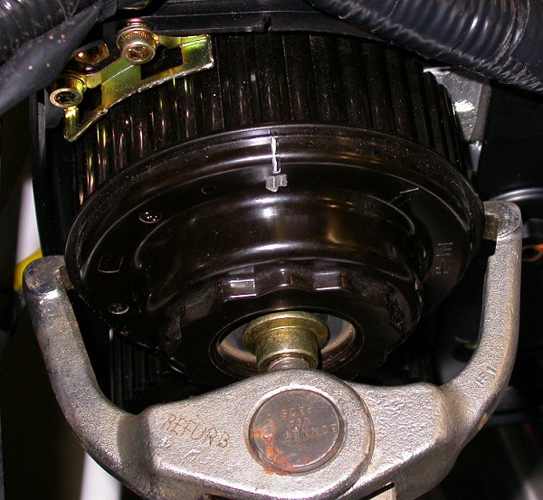
 This sprocket was on very tight, a quite snug press fit, but very
fortunately, this sprocket is steel, with the 5 lightening holes, so I was
able to get a 3-leg puller in there and pop it off. The bolt hole is
bigger than the puller bolt, so I put the old bolt into the bolt hole and
pulled against that. I made up the little steel plate to sit on
the bolt head, so the puller bolt wouldn't enter the bolt allen head.
At first, the puller bolt was trying to screw into the allen head, and it
was messing things up. If you're wondering how I could pull the
sprocket with the bolt installed, it's because the bolt is actually about
1/4" from being tight against the sprocket, even though it doesn't look it
in this pic.
This sprocket was on very tight, a quite snug press fit, but very
fortunately, this sprocket is steel, with the 5 lightening holes, so I was
able to get a 3-leg puller in there and pop it off. The bolt hole is
bigger than the puller bolt, so I put the old bolt into the bolt hole and
pulled against that. I made up the little steel plate to sit on
the bolt head, so the puller bolt wouldn't enter the bolt allen head.
At first, the puller bolt was trying to screw into the allen head, and it
was messing things up. If you're wondering how I could pull the
sprocket with the bolt installed, it's because the bolt is actually about
1/4" from being tight against the sprocket, even though it doesn't look it
in this pic.
 On the LT side, there was nothing at all to get a puller onto. I
initially tried to use a 2-leg puller to get around on the back of the
sprocket. That didn't work, so I used the little lip, as shown here.
This sprocket is some sort of plastic, so I figured it might break the lip,
but at that point, I didn't care - I just had to get the damn thing OFF.
It came off easily, with no damage to the sprocket, so that was a big relief. Quite fortunately,
this sprocket wasn't on nearly as tight as the RT one, although it was too
tight to pull off by hand without a puller. You can also
see where Eggenfellner has modified the hash marks, and turned the single
hash mark at the top of the sprocket into a double hash mark. That's
why it has to come off; so the Eggenfellner double hash mark is at the
bottom, aligned with the double hash mark on the lower sprocket, instead of
on top, as it is now.
On the LT side, there was nothing at all to get a puller onto. I
initially tried to use a 2-leg puller to get around on the back of the
sprocket. That didn't work, so I used the little lip, as shown here.
This sprocket is some sort of plastic, so I figured it might break the lip,
but at that point, I didn't care - I just had to get the damn thing OFF.
It came off easily, with no damage to the sprocket, so that was a big relief. Quite fortunately,
this sprocket wasn't on nearly as tight as the RT one, although it was too
tight to pull off by hand without a puller. You can also
see where Eggenfellner has modified the hash marks, and turned the single
hash mark at the top of the sprocket into a double hash mark. That's
why it has to come off; so the Eggenfellner double hash mark is at the
bottom, aligned with the double hash mark on the lower sprocket, instead of
on top, as it is now.
Dec 6 - Things went better than expected last night, trying to remove those sprockets. I feel much better about all this today than I did yesterday. I didn't do any engine work today - waiting for Jan to release his STi upgrade instructions. Update web site. 1.0 hr doc
Dec 7 - Pearl Harbor Day. Still waiting for Jan to release his upgrade instructions. Got tired of waiting & asked Robert Paisley if there was anything unusual or non-standard about reinstalling the cam belt & covers. Robert said there was not, so I got my parents to help me by holding the 2 RT sprockets, and I got the belt on in about half an hour. Replacing it later as part of routine maintenance is going to be a bitch, because the present gap between the engine and firewall is going to be filled with stuff like the supercharger, intercooler, and related plumbing. Using the sprocket mount bolts to turn and hold the RT sprockets was super easy, so no special tools needed. Update web site. 0.5 hr + 1.0 hr doc
Dec 8 - I had suggested to Jan that he adopt my idea, of using the cam belt locked to the crank and the cam sprockets, to hold the sprockets for removal and for retorquing after installation. He expressed concern about overstressing the belt by doing that. So, I did not yet retorque my cam sprocket bolts. I also want to do the "belt teeth between each sprocket" count, as specified in the Subaru manual, before I am completely confident that the belt is on correctly and torque the bolts and put the covers back on. I checked the belt alignment and it looked good, so I pulled the pin on the tensioner. As soon as I did that, it seemed to me that all the alignment marks were OK, except the double lines aligning the RT sprockets appeared to be off by 1/2 tooth. I unlocked the crank and rotated it through one revolution, to help equalize tension on the belt. Then I checked the alignments again , and they seemed OK. Web site updates. 0.5 hr + 0.5 hr doc
Dec 9 - Work on Eggenfellner Installation Manual. Torque sprocket bolts, with blue Loctite, using the cam belt to hold the sprockets. Then, I got to worrying about what Jan had said about overstressing the belt, so I called the Subaru dealer. They had the belt in stock, but it was $190. I asked their service dept guy if he thought what I'd done would overstress the belt, and he said it would, so I bought a new belt and installed it, with my parents' help again. 2.5 hr + 5.0 hr doc (Eggenfellner Manual)
Dec 10 - Cut the inlet neck off the intercooler, and measured and marked it for rewelding. Retorqued Belt Idler A and tensioner bolts (28 ft lb). Set belt guards and torqued them to 61 in lb. Reinstalled cam belt covers and torqued to 43 in lb. On the center cover, some of the bolts are hard to see, so make sure you get all 8. Remounted supercharger, and started working on fixing the clearance issues with that. Also realized I never got an alternator belt. Emailed Jan about it & he will send it, along with some additional SC-IC plumbing tubing I will need. Repeatedly marked and ground clearance problems between top of supercharger and bottom of cam cover, until I had enough supercharger adjustment movement to allow me to get the belt on and to tension it. Then worked on fixing fit problems with SC-IC plumbing, as well as clearance and fit problems with SC belt tensioner rod. 6.0 hr
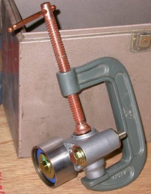 Someone suggested using a big C clamp to slowly compress the cam belt
tensioner, so I tried that. I personally preferred using the bench
vise.
Someone suggested using a big C clamp to slowly compress the cam belt
tensioner, so I tried that. I personally preferred using the bench
vise.
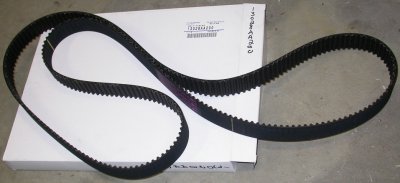 I
plunked down almost $200 to pay for a new timing belt, rather than take a
chance that the old one got overstressed when I used it to loosen and
tighten the cam sprocket bolts. That sucked, but I just couldn't take
the chance on an overstressed belt breaking. Jan later said he could
get these from Subaru for much less than $180. The local Subaru
dealer, Subaru of Claremont, is a notorious crook, anyway.
I
plunked down almost $200 to pay for a new timing belt, rather than take a
chance that the old one got overstressed when I used it to loosen and
tighten the cam sprocket bolts. That sucked, but I just couldn't take
the chance on an overstressed belt breaking. Jan later said he could
get these from Subaru for much less than $180. The local Subaru
dealer, Subaru of Claremont, is a notorious crook, anyway.
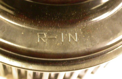
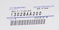 Here's a closeup of the Subaru ID tag for the cam timing belt.
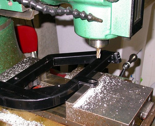
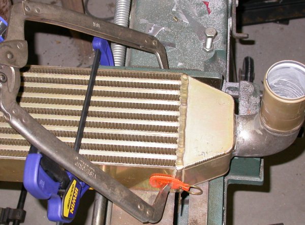 After removing the built-in clamping for the bandsaw, I managed to get the intercooler chucked up into the bandsaw, and here I've
started cutting off the inlet tubing. I was able to put the welded-on
tab into the slot for the work clamp, and get it all lined up where I needed
it.
After removing the built-in clamping for the bandsaw, I managed to get the intercooler chucked up into the bandsaw, and here I've
started cutting off the inlet tubing. I was able to put the welded-on
tab into the slot for the work clamp, and get it all lined up where I needed
it.
 Cutting off the intercooler inlet neck, to get it rewelded at a more fwd
angle
Cutting off the intercooler inlet neck, to get it rewelded at a more fwd
angle
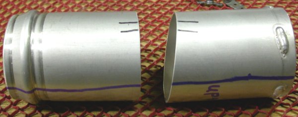
 Intercooler inlet neck cut off
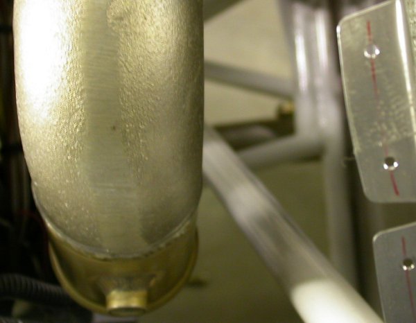
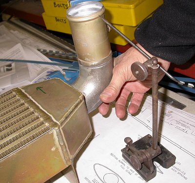 I used this tool to note the original position of the end of the neck, then
I rotated it so the neck is 7/8" more fwd. The green arrow helps make
sure I move it in the right direction.
I used this tool to note the original position of the end of the neck, then
I rotated it so the neck is 7/8" more fwd. The green arrow helps make
sure I move it in the right direction.
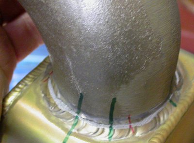 Multiple alignment marks help make sure it gets rewelded back on right where
I want it. I hate sending out jobs like this, when I could probably do
it OK, but sometimes my TIG welding is good and sometimes it isn't.
I'd sure hate to mess this up, so I am paying for a welding shop to do it.
Multiple alignment marks help make sure it gets rewelded back on right where
I want it. I hate sending out jobs like this, when I could probably do
it OK, but sometimes my TIG welding is good and sometimes it isn't.
I'd sure hate to mess this up, so I am paying for a welding shop to do it.
 The first time I removed and replaced the cam timing belt, I did not bother
loosening the belt guides, in the foreground here. The second time I
did it, I decided it would be easier to put the new belt in if I didn't have
to work around the guides, so I loosened them. To reinstall them, the
Subaru manual calls for 0.040" +- 0.020" gap between the belt and
the guide. So, I took a scrap
piece of 0.032" sheet, bent it to match the sprocket radius, pushed the
guide up against the metal against the belt, and torqued the guide bolts.
The first time I removed and replaced the cam timing belt, I did not bother
loosening the belt guides, in the foreground here. The second time I
did it, I decided it would be easier to put the new belt in if I didn't have
to work around the guides, so I loosened them. To reinstall them, the
Subaru manual calls for 0.040" +- 0.020" gap between the belt and
the guide. So, I took a scrap
piece of 0.032" sheet, bent it to match the sprocket radius, pushed the
guide up against the metal against the belt, and torqued the guide bolts.
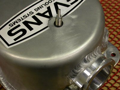
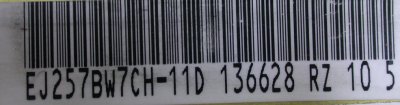 This sticker was on my timing cover, and it identifies my engine, so I
wanted to be sure to record that info.
This sticker was on my timing cover, and it identifies my engine, so I
wanted to be sure to record that info.
 The supercharger only had 1/16" of belt adjustment play available, so I had
to open that up some. Here, I have used a points file to mark
where the top of the SC is hitting the bottom of the cam timing cover
plastic backing plate. Someone had complained that their engine came
with a big hole ground in the bottom of the cam cover, to accommodate this.
By careful and limited grinding on both the bottom of the cam over and the
top of the supercharger, I planned to increase travel enough to get the belt
on and to be able to tighten it, without making a hole in the cover.
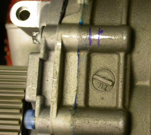
The blue marks define the lateral limits of where it hits the bottom of the
cover.
The supercharger only had 1/16" of belt adjustment play available, so I had
to open that up some. Here, I have used a points file to mark
where the top of the SC is hitting the bottom of the cam timing cover
plastic backing plate. Someone had complained that their engine came
with a big hole ground in the bottom of the cam cover, to accommodate this.
By careful and limited grinding on both the bottom of the cam over and the
top of the supercharger, I planned to increase travel enough to get the belt
on and to be able to tighten it, without making a hole in the cover.
The blue marks define the lateral limits of where it hits the bottom of the
cover.
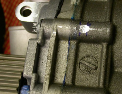 Here is is after grinding it down a bit, to give me a little more clearance.
I ground some off the bottom of the cam cover backer, too, but not enough to
create an opening through the cover or backer.
Here is is after grinding it down a bit, to give me a little more clearance.
I ground some off the bottom of the cam cover backer, too, but not enough to
create an opening through the cover or backer.
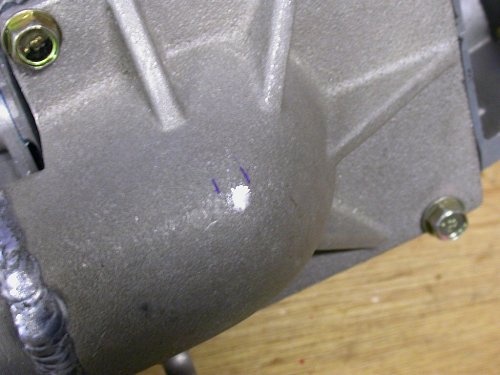 I used the points file again to mark the interference at the bottom of the supercharger, where the bottom of
it hits the engine frame.
I used the points file again to mark the interference at the bottom of the supercharger, where the bottom of
it hits the engine frame.
![]() After numerous iterations of mark, grind, fit, I ended up with this.
My supercharger belt adjustment range has gone from 1/16" to 1/4"; probably
just enough. The different color marks show how the lateral limits
where I needed to file changed as the SC swung down slightly more
After numerous iterations of mark, grind, fit, I ended up with this.
My supercharger belt adjustment range has gone from 1/16" to 1/4"; probably
just enough. The different color marks show how the lateral limits
where I needed to file changed as the SC swung down slightly more
![]() This is how much clearance I now have with the SC belt on and the SC hanging
down against the belt. It's probably just barely enough to add a
little tension to the belt, without filing away any more than necessary.
This is how much clearance I now have with the SC belt on and the SC hanging
down against the belt. It's probably just barely enough to add a
little tension to the belt, without filing away any more than necessary.
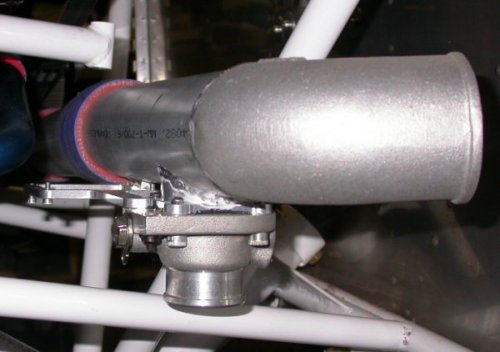
 Next fit problem: the cast aluminum ell that's welded to the SC does
not come off the SC at a right angle, as shown here. It points too
much aft, toward the engine frame. I was considering cutting it off
and rewelding it at a more nearly 90 degree angle, but I subsequently found
that the play allowed by the silicone fittings will allow me to just miss
the frame.
Next fit problem: the cast aluminum ell that's welded to the SC does
not come off the SC at a right angle, as shown here. It points too
much aft, toward the engine frame. I was considering cutting it off
and rewelding it at a more nearly 90 degree angle, but I subsequently found
that the play allowed by the silicone fittings will allow me to just miss
the frame.
 Next problem - the supercharger belt tension adjuster rod is too long.
The bolt is supposed the go through the white frame piece there. This
pic is with one jam nut installed. Even with both jam nuts
removed and both rod ends screwed all the way in, it's about 3/8" too long.
Because both rod ends are right-hand thread, a jam nut isn't really
necessary, as one end loosening will tighten the other end until it bottoms
out. With both rod ends bottomed out, there's no place for anything to
unscrew. Jan said the rod end should be installed on the BOTTOM part of the frame.
I subsequently found a better fit (and the rod is now just barely short
enough) if I put the rod end on the TOP of the frame. The only problem
with that is now the rod hits on the coolant drain plug.
Next problem - the supercharger belt tension adjuster rod is too long.
The bolt is supposed the go through the white frame piece there. This
pic is with one jam nut installed. Even with both jam nuts
removed and both rod ends screwed all the way in, it's about 3/8" too long.
Because both rod ends are right-hand thread, a jam nut isn't really
necessary, as one end loosening will tighten the other end until it bottoms
out. With both rod ends bottomed out, there's no place for anything to
unscrew. Jan said the rod end should be installed on the BOTTOM part of the frame.
I subsequently found a better fit (and the rod is now just barely short
enough) if I put the rod end on the TOP of the frame. The only problem
with that is now the rod hits on the coolant drain plug.
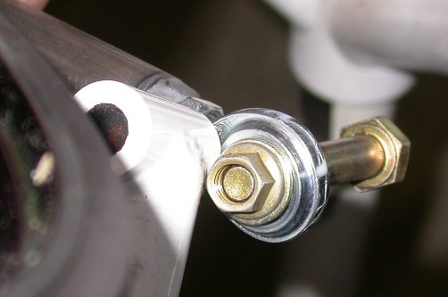
![]() This pic shows how the rod at "B" hits the square wrenching part of the
coolant drain plug when the inboard end of the rod is mounted to the TOP of
the frame, at "A". I am currently trying to find a 3/4" NPT plug with
internal wrenching, which will solve this problem.
This pic shows how the rod at "B" hits the square wrenching part of the
coolant drain plug when the inboard end of the rod is mounted to the TOP of
the frame, at "A". I am currently trying to find a 3/4" NPT plug with
internal wrenching, which will solve this problem.
Dec 11 - Installed SC/alternator drive pulley to crank & torqued to 133 ft lb. Removed jam nut from SC tension rod to try to make it shorter. Remove eyebolt on SC and add a couple washers, to eliminate interference between the rod end and the bottom of the SC. SC tension rod now is barely short enough if I mount it to the TOP of the frame, rather than the BOTTOM, where Jan says it's supposed to go. If I try to mount it to the bottom, it's still about 3/8" too long. I think mounting it to the top will also give me better clearance for the SC-IC plumbing, but I'll have to replace the coolant drain plug to do that. Working on installing SC inlet ducting. It looked plenty long enough before I installed it, but once it wraps around the curves it needs to go through, it's a tad short. It also fits poorly - too big for the fittings it goes on. I clamped one end down tight & later discovered it mangled the internal support wires and even crunched a hole in the duct. Will have to get a new one, a couple inches longer, from Jan. It's 14" long and should be 16" long to fit properly. I am working on getting the supercharger to intercooler plumbing to fit. It seems to interfere with the frame in several places. The wastegate parts seem to be in the way, too, and I don't know what gets mounted to the wastegate. It looks like it's designed for something to be mounted there. 1.0 hr
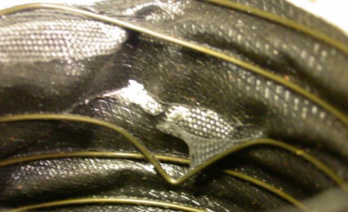 This shows where the tightened hose clamp mangled the support wires and tore
the duct, because it's too big for where it needs to go.
This shows where the tightened hose clamp mangled the support wires and tore
the duct, because it's too big for where it needs to go.
![]() Also, at the SC end of the belt adjustment rod, the top of the rod end was
binding against the bottom of the SC. I fixed that by adding 2
washers, as shown here. One washer gave me the clearance I needed, but 2
were needed to get the eyebolt alignment back where I wanted it when the
eyebolt is tight. Or I could have ground down the OD of the rod end a
bit.
Also, at the SC end of the belt adjustment rod, the top of the rod end was
binding against the bottom of the SC. I fixed that by adding 2
washers, as shown here. One washer gave me the clearance I needed, but 2
were needed to get the eyebolt alignment back where I wanted it when the
eyebolt is tight. Or I could have ground down the OD of the rod end a
bit.
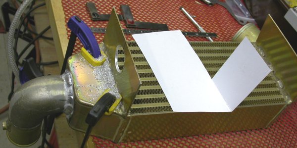
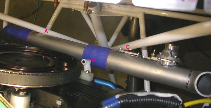 Here is an overhead view of the current installation dilemma, looking down.
The supercharger is on the far LT of the pic. The SC-IC plumbing is hitting the frame at A. B, and C. "A" is
not a big problem, as the play allowed by the silicone fittings will let me
push the tubing fwd away from "A" a bit. That in turn
pushes it more into the frame at "B". If I push the tubing down at "B
to clear it more, it increases the interference at "A", due to the angle of
the diagonal. I plan to solve the interference at "B" by putting the
SC belt tension adjuster rod end on TOP of the frame at "B", rather than the
bottom, where Jan says it is supposed to go. This will let the tubing
go directly under "B, without interfering with the adjuster rod. Now,
I am stuck with the interference at "C". Those wastegate parts are
interfering big time with the diagonal. I emailed Jan with several
questions, including how this is supposed to fit and what the square cutout
part of the wastegate (opposite "C" here) is for.
Here is an overhead view of the current installation dilemma, looking down.
The supercharger is on the far LT of the pic. The SC-IC plumbing is hitting the frame at A. B, and C. "A" is
not a big problem, as the play allowed by the silicone fittings will let me
push the tubing fwd away from "A" a bit. That in turn
pushes it more into the frame at "B". If I push the tubing down at "B
to clear it more, it increases the interference at "A", due to the angle of
the diagonal. I plan to solve the interference at "B" by putting the
SC belt tension adjuster rod end on TOP of the frame at "B", rather than the
bottom, where Jan says it is supposed to go. This will let the tubing
go directly under "B, without interfering with the adjuster rod. Now,
I am stuck with the interference at "C". Those wastegate parts are
interfering big time with the diagonal. I emailed Jan with several
questions, including how this is supposed to fit and what the square cutout
part of the wastegate (opposite "C" here) is for.
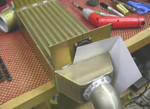
 I asked Jan if I could solve the frame diagonal interference problem by
having all that wastegate stuff on the BOTTOM of the tube, rather than on
the aft side of it, where it interferes with the diagonal, as shown here.
Of course, if I do that, the cast aluminum ell will have to be cut off and
rewelded back on so it is pointing UP. This also seems to me to be a
more natural exit attitude for the wastegate. I'll wait & see what
reply Jan comes back with.
I asked Jan if I could solve the frame diagonal interference problem by
having all that wastegate stuff on the BOTTOM of the tube, rather than on
the aft side of it, where it interferes with the diagonal, as shown here.
Of course, if I do that, the cast aluminum ell will have to be cut off and
rewelded back on so it is pointing UP. This also seems to me to be a
more natural exit attitude for the wastegate. I'll wait & see what
reply Jan comes back with.
Dec 12 - I also have no idea how the intercooler is supposed to be mounted. I think the best way is to weld a plate to the back of the intercooler, including the 2 big tabs already welded onto it, and then bolt that to the firewall, using backing plates on the other side of the firewall. I asked about all that to Jan & the STi group; waiting now for responses. Update web site 3.0 hr doc
Dec 13 - I got some answers back from Jan. He says I should make an ell bracket to mount the intercooler. Why the heck didn't he provide it with the kit? He says the square machined part of the wastegate mount frame used to be for a servo, and is no longer needed. So, I can cut that off. That'll help a lot with the interference. Jan is also sending me my alternator belt and another piece of the intercooler plumbing tubing. He mentioned to mount the wastegate pointing at least slightly downward, so rain water can't get into it. He said this about how to mount the intercooler: A hole is made at the center of each of the inter cooler vertical plates. The holes are large enough to clear the rubber of the Lord mounts. Then the mount is riveted or bolted to each plate. Two angles are riveted to the firewall (or nut plates). These reach out and parallel the lord mounts. A single 1/4 bolt is used at each end of the cooler, through the lord mount and firewall angle brace. the cooler is kept from tilting about its center when it is attached to the throttle body. I ordered an aluminum AN 3/4" NPT plug with internal Allen wrenching over the Internet from Thunder Racing. They had the best prices & terms I found in a Google search. It's $25 with shipping, but what can I do? I should have that in a couple days, and then I can mount the SC belt adjustment rod without interfering with the coolant drain plug.
Dec 14 - It was so cold last night (below zero) that I didn't feel like going out into the garage. I've been negotiating with the City of Claremont on getting the lease finalized for my hangar construction. Those bureaucrats are amazing at how long it takes them to do the simplest things or make the most obvious decisions. How do they live with themselves? It must take some special rationalization. It's below zero again this evening. Cranked up the heater & worked on plane awhile. Measured SC inlet fitting and ducting. No wonder it doesn't fit well; the fittings are 2.75" and the ducting is 3". I made a note to email Jan about getting some more of proper diameter. I noted that the ACS catalog lists 2.75" ducting, so I know the proper diameter IS available. I also got ready to cut off the excess part of the wastegate frame (where the old servo was to be mounted), but then got to thinking I might need some of that frame to secure the wastegate cable housing. Also wondering if the small brass barbed fitting is still used, and for what. Measured for big Adel clamps to buy to secure this plumbing when I get it installed. More web page updates. 1.5 hr + 1.5 hr doc
 Jan says
the square machined part was for a servo that is no longer used. I
wonder how parts can get obsolete so fast, as I am one of the first to
install all this, but I try not to think about stuff like that, as I just
get irritated and it doesn't help get this done. This engine is
definitely a work in progress. I started to get ready to cut the
wastegate servo frame off, for better clearance to the engine frame, but
decided to wait. I may need part of that frame to mount a clamp
for the cable housing for the wastegate actuating cable. The black
thing was probably an adjustable stop for the servo. I don't
know what the brass barbed fitting is for. Queried Jan and STi
list on these things. Jan later said the brass barbed fitting is no
longer used, so I put an aluminum plug in there.
Jan says
the square machined part was for a servo that is no longer used. I
wonder how parts can get obsolete so fast, as I am one of the first to
install all this, but I try not to think about stuff like that, as I just
get irritated and it doesn't help get this done. This engine is
definitely a work in progress. I started to get ready to cut the
wastegate servo frame off, for better clearance to the engine frame, but
decided to wait. I may need part of that frame to mount a clamp
for the cable housing for the wastegate actuating cable. The black
thing was probably an adjustable stop for the servo. I don't
know what the brass barbed fitting is for. Queried Jan and STi
list on these things. Jan later said the brass barbed fitting is no
longer used, so I put an aluminum plug in there.
![]() This is a pic of the grinding I did and the clearance I ended up with at the
top of the SC. The SC only needs to get tipped UP enough to be able to
get the belt on. This is with the SC swung down to its lowest
position, with the bottom of the SC outlet resting on the engine frame.
On the plastic part at the top, I only ground away the lip; no more.
So, there is no hole in any of the plastic, for dirt to get in.
This is a pic of the grinding I did and the clearance I ended up with at the
top of the SC. The SC only needs to get tipped UP enough to be able to
get the belt on. This is with the SC swung down to its lowest
position, with the bottom of the SC outlet resting on the engine frame.
On the plastic part at the top, I only ground away the lip; no more.
So, there is no hole in any of the plastic, for dirt to get in.
![]() This is also taken with the SC all the way down to its lowest position, with
the belt off, resting on the engine frame. The different color marks
indicate where the contact point changed as I ground away metal, and the SC
started swinging down a bit more. A previous pic showed how much
clearance (about 1/16" or less) is there when the belt is on.
This is also taken with the SC all the way down to its lowest position, with
the belt off, resting on the engine frame. The different color marks
indicate where the contact point changed as I ground away metal, and the SC
started swinging down a bit more. A previous pic showed how much
clearance (about 1/16" or less) is there when the belt is on.
![]() This is with the SC swung all the way up until it hits the cam cover.
This is the position for installing the belt. I have about 1/4"
clearance here - just enough to get the job done.
This is with the SC swung all the way up until it hits the cam cover.
This is the position for installing the belt. I have about 1/4"
clearance here - just enough to get the job done.
![]() This is what the final grinding (filing here, actually) ended up as.
This is what the final grinding (filing here, actually) ended up as.
![]() And this is the final amount of grinding (in conjunction with the grinding
of the bottom of the plastic cam cover backing plate) I needed to get the SC
up enough so the belt would just barely go on.
And this is the final amount of grinding (in conjunction with the grinding
of the bottom of the plastic cam cover backing plate) I needed to get the SC
up enough so the belt would just barely go on.
![]() This shows where the SC end of the SC belt tension adjuster rod interfered
with the SC. I added 2 washers to the eyebolt. I could have just
as easily done a little grinding here and/or on the OD of the rod end to
solve the problem.
This shows where the SC end of the SC belt tension adjuster rod interfered
with the SC. I added 2 washers to the eyebolt. I could have just
as easily done a little grinding here and/or on the OD of the rod end to
solve the problem.
Dec 15 - Jan had already emailed me & suggested that perhaps I had 3" ducting, and he said he'd send me some 2.75". Sent numerous other questions to Jan & STi list. Still waiting for my 3/4" NPT aluminum internal wrench coolant drain plug. UPS tracking says I have to wait to Monday (19th) to get it. That sucks. Jan also says that Robert is currently debugging the wastegate control scheme, so I am waiting for that to be completed, before I can proceed with fitting the wastegate. I'd wondered which way the engine turns when it runs, and Jan says the SC pulley will turn CLOCKWISE. He also says the small brass barbed fitting on the wastegate is no longer used. Jan says this about setting the supercharger belt to low tension:
When you say low tension, do you mean like just the weight of the SC hanging down against it?
Worked on intercooler mounting layout & laid out one one Lord mount. Updating web site. 2.25 hr + 2.0 hr doc
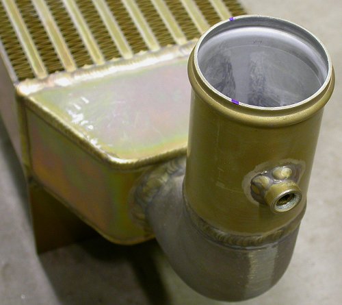
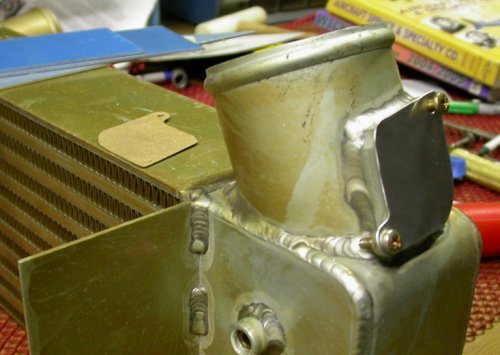
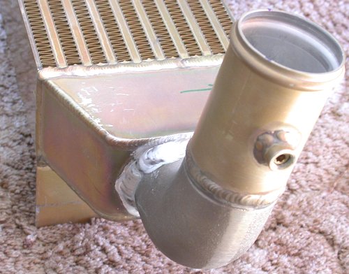 I went to the welding shop and picked up the rewelded intercooler. The
inlet neck now tips fwd so the end of it is 7/8" more fwd than it was
before, when it was welded on at 90 degrees. It sucks to pay to get
welding done that I could do, but sometimes my TIG welding goes well and
sometimes it does not, and I can't take chances with this stuff.
I went to the welding shop and picked up the rewelded intercooler. The
inlet neck now tips fwd so the end of it is 7/8" more fwd than it was
before, when it was welded on at 90 degrees. It sucks to pay to get
welding done that I could do, but sometimes my TIG welding goes well and
sometimes it does not, and I can't take chances with this stuff.
 What are these 2 plugged ports for?
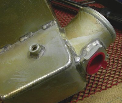
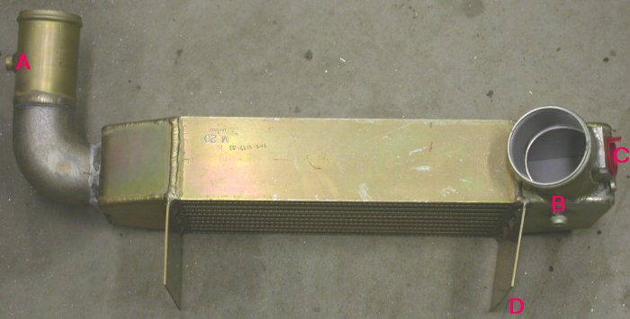 What is the purpose of the 3 plugged ports at A, B, and C? Is the tab
at D supposed to be bent like that, or is it shipping damage? I had
originally thought it was welded on like that for some reason, but now that
I know Jan's Lord mount scheme, it seems contrary to a Lord mount setup, and
I see no purpose for it being bent. All these are questions to be
posed to Jan & the STi list. I still don't understand why letters I
put on a pic (as the last step after cropping and resizing, and before
saving) look clear when I save them, and show up all fuzzy here.
What is the purpose of the 3 plugged ports at A, B, and C? Is the tab
at D supposed to be bent like that, or is it shipping damage? I had
originally thought it was welded on like that for some reason, but now that
I know Jan's Lord mount scheme, it seems contrary to a Lord mount setup, and
I see no purpose for it being bent. All these are questions to be
posed to Jan & the STi list. I still don't understand why letters I
put on a pic (as the last step after cropping and resizing, and before
saving) look clear when I save them, and show up all fuzzy here.
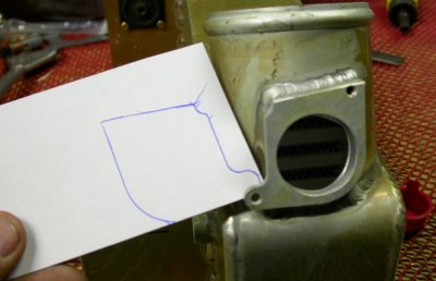
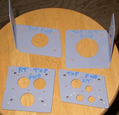
 Laying out and drilling the Lord mount for the LT side of the intercooler.
The white cardboard is the pattern I made for a LT bracket from which to
hang the intercooler. I ended up making it much shorter. I
had originally thought I'd need to tie it all the way down to the horizontal
angle across the firewall.
Laying out and drilling the Lord mount for the LT side of the intercooler.
The white cardboard is the pattern I made for a LT bracket from which to
hang the intercooler. I ended up making it much shorter. I
had originally thought I'd need to tie it all the way down to the horizontal
angle across the firewall.
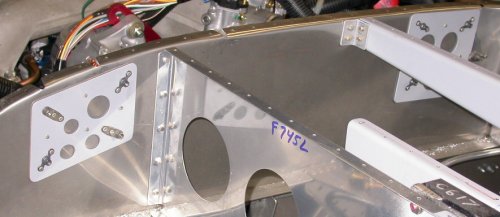
 Here is the LT Lord mount temporarily installed, centered on the intercooler
tab, with the cardboard mount bracket pattern in approximately the position
in which it will be mounted to the firewall and used to support the
intercooler.
Here is the LT Lord mount temporarily installed, centered on the intercooler
tab, with the cardboard mount bracket pattern in approximately the position
in which it will be mounted to the firewall and used to support the
intercooler.
Dec 16 - update web site & post email questions about intercooler. Robert Paisley says this about the intercooler questions: Plug all the ports except for B which can be used to measure intake air temp with one of your extra inputs on the EIS. Straighten the bent mounting tab by placing a 2x4 flat against it and tapping the 2x4. Something that looks like a shelf hanging bracket can be bolted to the firewall to extend out and provide a mating face next to each mounting tab on the intercooler with Lord instrument mounts between the plates. I believe you have pics of this from my installation. So, apparently that is a bent tab, and was not designed that way. Later, worked on plane more & straightened the bent tab. Made & installed cover for large hole at intercooler outlet. Install RT Lord mount to intercooler. Received my alternator belt (Dayco 5040270) and extra needed SC-IC plumbing parts from Eggenfellner. Tried to install alternator belt & found the belt is too small to go on over the SC pulley, as I'd suspected it might be. Cursed the air blue awhile, as I'd asked Jan if the belt would go on over the SC pulley before I installed the pulley, and Jan had said it would. It doesn't even come close to going on over the SC pulley. I guess Jan must have not understood my question. The pulley had been squeezed onto the shaft and torqued down, and I was concerned it would be a hassle to get it back off, and would need a puller to get it off. It turned out that the pulley simply slipped off the shaft after I removed the bolt - no tight fit, so it wasn't a big deal to take the pulley off, without a puller, to install the alternator belt. Reinstalled pulley and torqued bolt to 133 ft lb. Reinstalled RT cam cover. The SC belt goes on a bit harder with the RT cam cover on (slightly reduced clearance to the SC), but I got it on OK. Installed alternator belt and alternator. Made an alternator mount bushing for Jim Skala. 5.0 hr + 1.0 hr doc
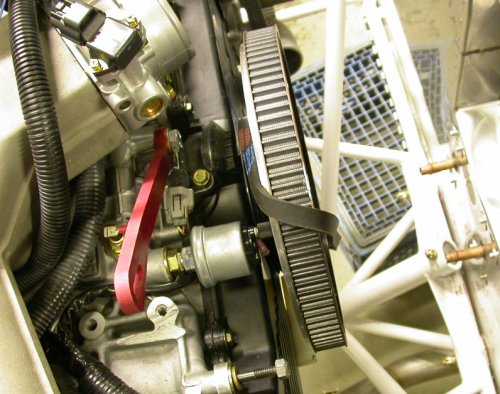
 This is one of the pictures Robert Paisley referred to, which I took of his
engine installation at OSH05. We can see here part of how he is
mounting the intercooler. Jan apparently changed it from a 4 Lord
mount system to one that uses just one Lord mount on each tab.
This is one of the pictures Robert Paisley referred to, which I took of his
engine installation at OSH05. We can see here part of how he is
mounting the intercooler. Jan apparently changed it from a 4 Lord
mount system to one that uses just one Lord mount on each tab.
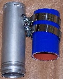 I got this 8" extension tube from Jan, along with the alternator belt.
This needs to run vertically from the wastegate piece that runs horizontally
across the engine compartment. Apparently, tailwheel planes don't have
as many cross braces in the engine frame, and they can go diagonally from
the SC to the IC. For nosewheel planes like mine, we have to go across
horizontally, then come straight up. Jan says this about all those
clamps for the SC-IC plumbing: Once you have assured that
the silicone hose protrudes a minimum of 3/16" beyond the clamp, and that
the entire width of the clamp is behind the barb on the tubing, torque to 50
inlb
I got this 8" extension tube from Jan, along with the alternator belt.
This needs to run vertically from the wastegate piece that runs horizontally
across the engine compartment. Apparently, tailwheel planes don't have
as many cross braces in the engine frame, and they can go diagonally from
the SC to the IC. For nosewheel planes like mine, we have to go across
horizontally, then come straight up. Jan says this about all those
clamps for the SC-IC plumbing: Once you have assured that
the silicone hose protrudes a minimum of 3/16" beyond the clamp, and that
the entire width of the clamp is behind the barb on the tubing, torque to 50
inlb
 Here is the pattern I made on a piece of cardboard for covering up that
unused port on the intercooler.
Here is the pattern I made on a piece of cardboard for covering up that
unused port on the intercooler.
 Here is the completed port cover, made from 0.040" 2024 sheet, temporarily
installed. I will seal between the intercooler and the cover with RTV
silicone sealant. The completed pattern lies on the top of the
intercooler.
Here is the completed port cover, made from 0.040" 2024 sheet, temporarily
installed. I will seal between the intercooler and the cover with RTV
silicone sealant. The completed pattern lies on the top of the
intercooler.
 The
alternator belt does not even come close to going on over the SC pulley.
I had wondered if it would, but Jan said it would, so I installed the pulley
before I got the alternator belt. Fortunately, pulling the SC
pulley back off was quite easy.
The
alternator belt does not even come close to going on over the SC pulley.
I had wondered if it would, but Jan said it would, so I installed the pulley
before I got the alternator belt. Fortunately, pulling the SC
pulley back off was quite easy.
 Alternator & belt installed & looking good. Tight fit on back side of
alternator, but it does all fit OK.
Alternator & belt installed & looking good. Tight fit on back side of
alternator, but it does all fit OK.
Dec 17 - Make & fit intercooler mount brackets. 4.25 hr
 Brackets clecoed into place, intercooler temporarily clamped to brackets
 Back view of intercooler mounting and brackets, showing backing plates I
used to spread the load over the thin firewall sheet metal. Plates and
brackets are 0.063" 2024T3.
Back view of intercooler mounting and brackets, showing backing plates I
used to spread the load over the thin firewall sheet metal. Plates and
brackets are 0.063" 2024T3.
Dec 18 - finish intercooler mount brackets. Install IC & brackets. Start looking at SC-IC plumbing & finalizing that fit. The 8" piece from Jan needs to be about 1" shorter. Mark & drill Lord mount holes & mount IC with AN4-11A bolts. Fit last 8" piece of SC-IC tubing - it needs 1/2" taken out of one side of middle, and it's now (after final IC install) about and inch too long. Cut notch out of tubing. Work on fitting tubing & notch, then realize how to do it better, so I cut the tubing twice at a 10 degree angle - an inch apart. Work on Adel clamps to support coolant line. Remove IC brackets for lightening holes and size/shape trimming. 8.25 hr
 There was originally 7/8" of overlap between the IC inlet casting and the
frame diagonal brace. Now the IC inlet casting clears the frame by
plenty - even more than I originally planned, and it worked out great that
way, as it now points directly at the wastegate tubing when the tubing is
located at it's most aft possible point.
There was originally 7/8" of overlap between the IC inlet casting and the
frame diagonal brace. Now the IC inlet casting clears the frame by
plenty - even more than I originally planned, and it worked out great that
way, as it now points directly at the wastegate tubing when the tubing is
located at it's most aft possible point.
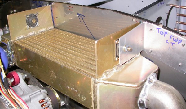
 With the intercooler inlet tipped fwd about an inch from perpendicular, it
points nicely at the tubing coming from the wastegate. The wastegate &
tubing can't go any more fwd, because the engine frame brace is in the way.
If the IC inlet was pointing straight down, the alignment would be very
poor.
With the intercooler inlet tipped fwd about an inch from perpendicular, it
points nicely at the tubing coming from the wastegate. The wastegate &
tubing can't go any more fwd, because the engine frame brace is in the way.
If the IC inlet was pointing straight down, the alignment would be very
poor.
![]() This is a view from the bottom, of how the wastegate machined frame parts are right up
against the engine frame tube. Jan says Robert is finalizing the redesign for the wastegate control, so I have to wait for that, to see how I need to mount
the cable to control the wastegate.
This is a view from the bottom, of how the wastegate machined frame parts are right up
against the engine frame tube. Jan says Robert is finalizing the redesign for the wastegate control, so I have to wait for that, to see how I need to mount
the cable to control the wastegate.
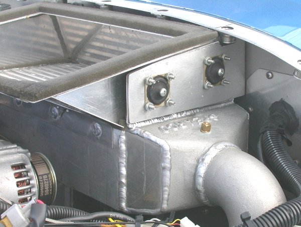
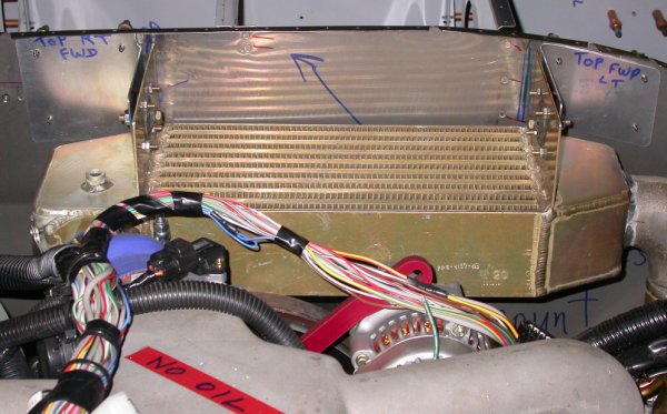 Here is the intercooler and brackets, mounted in final position. The
nuts are just temporary plain nuts for now. The final installation
will be all metal locknuts. You can also see that the LT side of the
intercooler (RT in this pic) is not tight against the firewall. This
was necessary so the connection from the intercooler to the intake manifold
was a more relaxed and natural alignment. It also brings the
intercooler inlet neck fwd away from interference with the 7A engine frame
diagonal brace.
Here is the intercooler and brackets, mounted in final position. The
nuts are just temporary plain nuts for now. The final installation
will be all metal locknuts. You can also see that the LT side of the
intercooler (RT in this pic) is not tight against the firewall. This
was necessary so the connection from the intercooler to the intake manifold
was a more relaxed and natural alignment. It also brings the
intercooler inlet neck fwd away from interference with the 7A engine frame
diagonal brace.
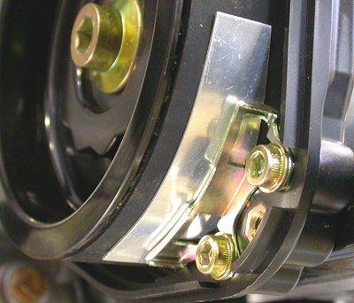
 close-up view of one side of the intercooler mounting
 Unfortunately, the camera didn't focus well, but you can see here the
remaining misalignment I have to finalize my SC-IC plumbing. There's
about a 1/4" gap at the top, on the aft side, and a 1/2" gap on the bottom,
on the outboard side. I'll cut, bend, and weld the pipe so the fit is
better.
Unfortunately, the camera didn't focus well, but you can see here the
remaining misalignment I have to finalize my SC-IC plumbing. There's
about a 1/4" gap at the top, on the aft side, and a 1/2" gap on the bottom,
on the outboard side. I'll cut, bend, and weld the pipe so the fit is
better.
 I did a 90 degree cut on the bandsaw, nearly all the way through, then
tipped the tubing up and cut it again, for my 1/2" of gap to resolve.
It's also about an inch too long, so I'll have to cut the end off and reweld
the hose grip weld beads.
I did a 90 degree cut on the bandsaw, nearly all the way through, then
tipped the tubing up and cut it again, for my 1/2" of gap to resolve.
It's also about an inch too long, so I'll have to cut the end off and reweld
the hose grip weld beads.
 After the above cutting & bending, I realized I can kill several birds with
one stone by simply cutting the tubing completely through, twice - an inch
apart, at about a 10 degree angle, and rotating the tube. I resolved
the "one inch too long" problem as I cut it, and I can end up with a bend in
2 directions at once, depending on how I rotate the 2 pieces. I ended
up with a very good fit this way, then I marked the pieces for alignment,
and will get them welded together this week.
After the above cutting & bending, I realized I can kill several birds with
one stone by simply cutting the tubing completely through, twice - an inch
apart, at about a 10 degree angle, and rotating the tube. I resolved
the "one inch too long" problem as I cut it, and I can end up with a bend in
2 directions at once, depending on how I rotate the 2 pieces. I ended
up with a very good fit this way, then I marked the pieces for alignment,
and will get them welded together this week.
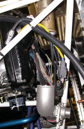
 I
started looking at getting the heater hoses installed to the heater. I
have 3 hoses hanging down now; one from the RT top "tower", and 2 from the
coolant pump. I am not presently sure where they all go or how they
go. Dec 30 update - heater hoses all installed now - the LT
one, from the RT engine top tower, goes to the RT fitting on the heater.
The middle one in the pic goes up to the bottom of the Moroso coolant
reservoir, and the one on the RT of the pic goes up to the heater LT
fitting.
I
started looking at getting the heater hoses installed to the heater. I
have 3 hoses hanging down now; one from the RT top "tower", and 2 from the
coolant pump. I am not presently sure where they all go or how they
go. Dec 30 update - heater hoses all installed now - the LT
one, from the RT engine top tower, goes to the RT fitting on the heater.
The middle one in the pic goes up to the bottom of the Moroso coolant
reservoir, and the one on the RT of the pic goes up to the heater LT
fitting.
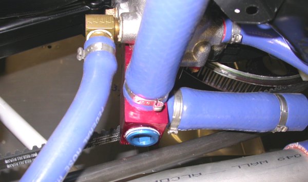
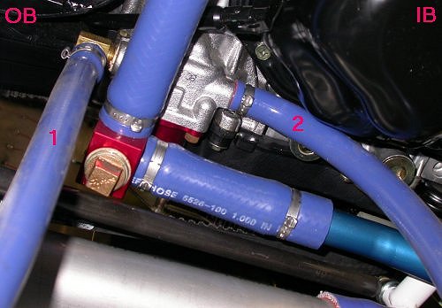 This is a view from the bottom or the engine, looking up at the coolant
pump. Inboard & outboard are labeled. #1 & #2 are the 2 heater
hoses currently hanging down. I have to connect these to the heater,
as well as reconnect the coolant reservoir. You can also see the
coolant drain plug interfering with the supercharger belt adjustment rod.
Dec 30 update - #1 goes to the bottom of the Moroso coolant reservoir.
I had to replace it with a longer hose, though. It used to go to the
tank OK, but that was before the SC, IC, and SC-IC plumbing was all
installed. After that, there is not enough length to go UNDER
the SC-IC plumbing shown at the bottom of this pic. Can't go over the
tube, because of interference with the SC belt. Definitely don't want
to be touching that! Hose #2 goes goes fwd, under the SC-IC tube, to
the heater LT fitting.
This is a view from the bottom or the engine, looking up at the coolant
pump. Inboard & outboard are labeled. #1 & #2 are the 2 heater
hoses currently hanging down. I have to connect these to the heater,
as well as reconnect the coolant reservoir. You can also see the
coolant drain plug interfering with the supercharger belt adjustment rod.
Dec 30 update - #1 goes to the bottom of the Moroso coolant reservoir.
I had to replace it with a longer hose, though. It used to go to the
tank OK, but that was before the SC, IC, and SC-IC plumbing was all
installed. After that, there is not enough length to go UNDER
the SC-IC plumbing shown at the bottom of this pic. Can't go over the
tube, because of interference with the SC belt. Definitely don't want
to be touching that! Hose #2 goes goes fwd, under the SC-IC tube, to
the heater LT fitting.
Dec 19 - order parts from ACS, Wicks. I may bitch sometimes about Jan and some of the things about his package that disappoint and annoy me, but Eggenfellner is a far cry above the competition. I am reading yet another email thread on the E-Subie list about how Crossflow has cheated its customers, taken money for engines not delivered, and left a string of very angry customers. They are being sued by several customers now, including one who used to be their biggest champion. NSI has had huge honesty and availability reputation problems for many years. The principals have been fired and are now facing criminal charges. The Innodyn engine has sounded good for years, but they seem to be going NOWHERE. Sure glad I didn't plunk my money down on THAT. Against all that, Jan Eggenfellner's honesty and availability are not even remotely in the same league. Jan's deserved reputation for honesty is unquestioned. Jan and his FWF are not perfect, but none of us are. Jan tries hard, and there is no doubt that people will get what they order and that Jan will stand behind what he sells and make things right. Jan makes himself available for help and support every day. Worked on lightening holes for intercooler mount brackets and backing plates. Update web site 1.0 hr + 3.0 hr doc
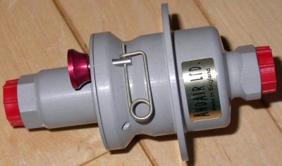 Finally got my Andair fuel filter. It was supposed to have come with
my engine in April, and I've been trying since then to get it. No
"inlet" indication or any other info with it, so I emailed Jan about it.
Jan replied with this info: The ANDAIR Ltd sticker
goes inside. Flange can be inside or outside but looks best outside.
Undo by pulling pin, rotate and pull apart. Rinse in gasoline.
Lubricate O-ring with fuel lube (Aircraft Spruce) and reinstall.
And I got this additional info from Ross Hauck:
The hex faces the engine, and the flange goes on the engine side of the
firewall. After removing the pin, you can rotate the outer body ccw to
disengage the locking lugs, and then pull apart fore/aft. You
don't want to hang a bunch of weight on the end of the filter, so run a flex
line from the filter to a firewall- mounted manifold, for fuel pressure
sensor, etc.
Finally got my Andair fuel filter. It was supposed to have come with
my engine in April, and I've been trying since then to get it. No
"inlet" indication or any other info with it, so I emailed Jan about it.
Jan replied with this info: The ANDAIR Ltd sticker
goes inside. Flange can be inside or outside but looks best outside.
Undo by pulling pin, rotate and pull apart. Rinse in gasoline.
Lubricate O-ring with fuel lube (Aircraft Spruce) and reinstall.
And I got this additional info from Ross Hauck:
The hex faces the engine, and the flange goes on the engine side of the
firewall. After removing the pin, you can rotate the outer body ccw to
disengage the locking lugs, and then pull apart fore/aft. You
don't want to hang a bunch of weight on the end of the filter, so run a flex
line from the filter to a firewall- mounted manifold, for fuel pressure
sensor, etc.
 Also received my order from Thunder Racing for the 3/4 NPT internal pipe
plug, along with a spare and a 1/2 NPT also. Now I can replace the
coolant drain plug and install the SC belt adjustment rod. I also
included some 1/8 NPT and 1/4 NPT internal AN plugs with my order from
Wicks.
Also received my order from Thunder Racing for the 3/4 NPT internal pipe
plug, along with a spare and a 1/2 NPT also. Now I can replace the
coolant drain plug and install the SC belt adjustment rod. I also
included some 1/8 NPT and 1/4 NPT internal AN plugs with my order from
Wicks.
Here is a series of questions and answers between me and Jan lately. I am posting them all here and in the Eggenfellner STi Upgrade chapter to make sure all the answers get documented.
Q: How is the SC belt tension set?
A: Set the belt tension so you can push it 1/2 " in the middle
without much effort. Robert found that his drive system operate best with
low tension. This is also best for the longevity of the supercharger
bearings.
Q: When you say low tension, do you mean like just the weight of the
SC hanging down against it?
A: No, you do need to pull with two hands to get the last tension rod
bolt in. A new belt will "set" into the pulleys quickly so a little tight
initially is no big deal. Then when running the engine inspect to see if the
belt wants to travel, slowly, back and fourth across the large pulley. This
would indicate perfect tracking.
Q: What gets bolted to the little square frame that's part of the
wastegate assy?
A: Nothing, used to be a servo but no longer needed. You can cut it
away
Q: What is the output of the wastegate; just a dump tube overboard?
Wouldn't I solve the frame diagonal interference problem by having all that
wastegate stuff on the BOTTOM of the tube, rather than on the aft side of
it, where it interferes with the diagonal?
A: I think you would find it much easier to run the tube straight
across the bottom of the firewall, rather than diagonal. Gives a little more
room. I have sent you the additional tube required for this. It might also
solve the dump valve interference issues. Yes, the dump valve just goes into
cowl area. It should be to the side or down to prevent rain water from
entering when parked.
Q: What holds the wastegate cable in place? Is there a
particular cable we are supposed to use for this? Is it supposed to be
part of the kit?
A: It is supposed to be installed after Robert has one flight tested.
Q: On the wastegate assy, there is a small barbed brass fitting. Is
this still used, or is it part of the obsolete servo?
A: Not used
Q: Regarding the ducting from radiator to SC:
A: This new style ducting is installed by bending the internal wire
back along the outside of the duct, far enough to hold it under the clamp.
This provides maximum support of the duct as it leaves the flange.
Q: How should I mount the intercooler?
A: A hole is made at the center of each of the inter cooler vertical
plates. The holes are large enough to clear the rubber of the Lord mounts.
Then the mount is riveted or bolted to each plate. Two angles are riveted to
the firewall (or nut plates). These reach out and parallel the lord mounts.
A single 1/4 bolt is used at each end of the cooler, through the lord mount
and firewall angle brace. the cooler is kept from tilting about its center
when it is attached to the throttle body.
Dec 20 - Debur intercooler mount bracket lightening holes. Prime brackets & backing plates. Rivet nutplates to backing plates. Install internal wrenching coolant drain plug. Install supercharger belt adjustment rod. Install, adjust & torque supercharger mount bolts. Rivet intercooler backing plates to firewall. Install intercooler. Update web site 4.25 hr + 1.0 hr doc
 Here are the primed intercooler mount brackets and the backing plates, with
nutplates riveted in place.
Here are the primed intercooler mount brackets and the backing plates, with
nutplates riveted in place.
 Here are the intercooler mount bracket backing plates, riveted to the aft
side of the firewall.
Here are the intercooler mount bracket backing plates, riveted to the aft
side of the firewall.
 This shows the new internal wrench coolant drain plug installed. The
supercharger belt adjustment rod is also now bolted into place, and it
clears the coolant drain plug OK.
This shows the new internal wrench coolant drain plug installed. The
supercharger belt adjustment rod is also now bolted into place, and it
clears the coolant drain plug OK.
Dec 21 - Get 8" extension tubing welded. Install SC-IC tubing & torque to #4 on my DeWalt drill. Install SC inlet air duct. Install RT header. Start mounting mufflers. Update web site 1.0 hr doc
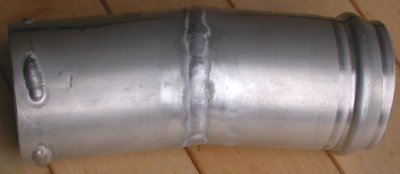 I've been trying for several days to get a welding shop to weld this up.
Last night, I tried to weld it myself, but it's so damn cold in *&^%$# NH
that my hands were numb by the time I got everything set up. I took it
to another welding shop this morning, and got it done. Because the
1/2" gap outboard and the 1/4" gap aft overlapped some, I ended up with less
apparent bend than you'd expect. It bends in 2 directions, for a
better fit between the wastegate tubing outlet and the intercooler inlet
neck, and it's an inch shorter than it was.
I've been trying for several days to get a welding shop to weld this up.
Last night, I tried to weld it myself, but it's so damn cold in *&^%$# NH
that my hands were numb by the time I got everything set up. I took it
to another welding shop this morning, and got it done. Because the
1/2" gap outboard and the 1/4" gap aft overlapped some, I ended up with less
apparent bend than you'd expect. It bends in 2 directions, for a
better fit between the wastegate tubing outlet and the intercooler inlet
neck, and it's an inch shorter than it was.
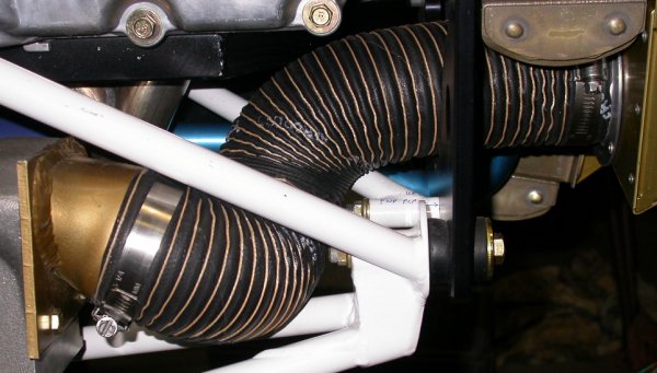 I finally got the SC inlet duct installed. It's a snug fit over the
radiator end, and a quite snug fit over the SC end. Also, the
alignment of the SC inlet is really bad. Instead of pointing inboard,
somewhat in the direction of the radiator, it points slightly outboard and
right at the engine frame junction in the middle of the pic, making the
installation much more challenging. This is yet another part of the
install that would be much easier if the SC was mounted a couple inches
inboard of where it is. I was tempted to remove the SC inlet and
weld a curve & extension onto it, so it points toward the radiator outlet,
but I got it done (for now) this way. Anyway, I finally got the
ducting on, then twisted it so it isn't rubbing on those 2 bolt ends coming
through the engine mount frame. It is now pressed against the frame
tubes, though, so I will have to deal with that.
I finally got the SC inlet duct installed. It's a snug fit over the
radiator end, and a quite snug fit over the SC end. Also, the
alignment of the SC inlet is really bad. Instead of pointing inboard,
somewhat in the direction of the radiator, it points slightly outboard and
right at the engine frame junction in the middle of the pic, making the
installation much more challenging. This is yet another part of the
install that would be much easier if the SC was mounted a couple inches
inboard of where it is. I was tempted to remove the SC inlet and
weld a curve & extension onto it, so it points toward the radiator outlet,
but I got it done (for now) this way. Anyway, I finally got the
ducting on, then twisted it so it isn't rubbing on those 2 bolt ends coming
through the engine mount frame. It is now pressed against the frame
tubes, though, so I will have to deal with that.
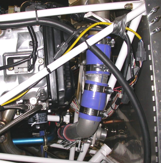 Here is all the SC-IC plumbing installed
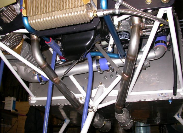 Here
is a big pic showing a good overall view (from below) of all my work today.
The SC-IC plumbing is all in. The SC is mounted and the belt adjusted.
The SC belt adjuster is clearing the coolant drain. The RT header is
back on. The mufflers are temporarily mounted as I get ready to mount
them. The 3 radiator hoses are hanging down, waiting for me to
figure out what goes where. The SC inlet duct is installed. I
plan to use the open triangular part of the engine frame (at RT in pic) to
mount my Accusump, which I ordered
today from a dealer on ebay. Given what Gary said about mounting the
mufflers (just hanging off headers, rather than weight supported by Lord
mounts), the existing header config may be OK, and I may not need to get
them rewelded. The balance point of the mufflers is 9" back from the
firewall. To use one center Lord mount and clear the fuel pumps would
require that the clamp be 12.75" back, so I will be using 2 outboard mounts,
rather than one in the center. I had preferred that the mount(s)
be in the center, to avoid being under my feet, but I guess that's
unavoidable. I think hanging the full weight of the mufflers off the
headers is a bad idea, and will cause the headers to crack, so I will
support most of the weight by the Lord mounts. Also, the muffler
clamps seem to be too small - I can't get the nut on. Will retry
tomorrow.
Here
is a big pic showing a good overall view (from below) of all my work today.
The SC-IC plumbing is all in. The SC is mounted and the belt adjusted.
The SC belt adjuster is clearing the coolant drain. The RT header is
back on. The mufflers are temporarily mounted as I get ready to mount
them. The 3 radiator hoses are hanging down, waiting for me to
figure out what goes where. The SC inlet duct is installed. I
plan to use the open triangular part of the engine frame (at RT in pic) to
mount my Accusump, which I ordered
today from a dealer on ebay. Given what Gary said about mounting the
mufflers (just hanging off headers, rather than weight supported by Lord
mounts), the existing header config may be OK, and I may not need to get
them rewelded. The balance point of the mufflers is 9" back from the
firewall. To use one center Lord mount and clear the fuel pumps would
require that the clamp be 12.75" back, so I will be using 2 outboard mounts,
rather than one in the center. I had preferred that the mount(s)
be in the center, to avoid being under my feet, but I guess that's
unavoidable. I think hanging the full weight of the mufflers off the
headers is a bad idea, and will cause the headers to crack, so I will
support most of the weight by the Lord mounts. Also, the muffler
clamps seem to be too small - I can't get the nut on. Will retry
tomorrow.
Dec 22 - update web site 0.5 hr doc
Dec 23 - Torque intercooler plumbing clamps to 50 in lb. Grind all sharp corners of supercharger lower fwd housing and SC inlet plate. Install header braces. Found it would have been MUCH easier to have put the header brace bolt in BEFORE putting on the crank pulley. Access is now very tight in there. Install header nuts. Found the new SC bracket is slightly closer to the inboard nut & stud on RT header, so there's no way to get a socket onto it. No way to get a wrench on it, either. Drove to Lebanon Sears & bought some metric crowfoot sockets. If that doesn't work, I have some thinner wall 10mm nuts I can use there - they take a 14mm wrench instead of the current 17mm. Header torque value is 25 ft lb. 3.0 hr
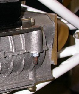 See all the untrimmed sharp corners on the supercharger and the SC inlet.
They take up space for getting your hand in there, especially on the back
side, they are sharp, with no deburring whatsoever done to them, and they
add a bit of weight.
See all the untrimmed sharp corners on the supercharger and the SC inlet.
They take up space for getting your hand in there, especially on the back
side, they are sharp, with no deburring whatsoever done to them, and they
add a bit of weight.
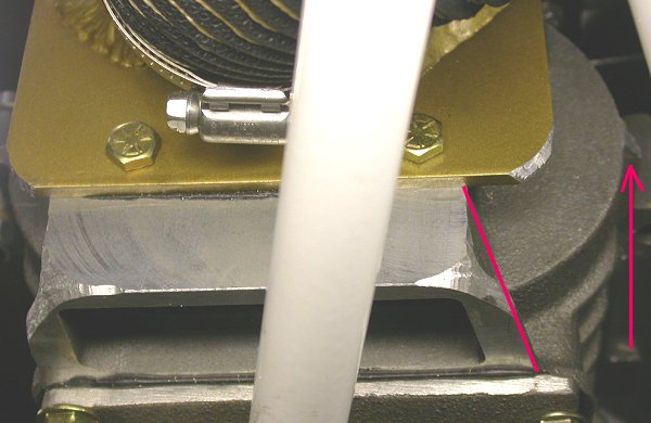 This pic shows where I cut away the sharp corners of both the fwd bottom of
the supercharger, as well as the 4 corners of the SC inlet plate. I
highly recommend grinding all this excess material away BEFORE mounting the
SC. The arrow points toward the sharp end corner of a reinforcing rib
on the SC that I also ground to a rounded edge. All those sharp
corners make working in there more difficult, plus all that excess material
is just taking up useless space and weight. I started all this
grinding after bumping my head once on the sharp corner of the SC inlet
plate. The SC inlet plate should really be ground all the way back to
the supercharger frame outline. The supercharger lower fwd part could
also be completely trimmed off at a diagonal, as shown by the red line.
This pic shows where I cut away the sharp corners of both the fwd bottom of
the supercharger, as well as the 4 corners of the SC inlet plate. I
highly recommend grinding all this excess material away BEFORE mounting the
SC. The arrow points toward the sharp end corner of a reinforcing rib
on the SC that I also ground to a rounded edge. All those sharp
corners make working in there more difficult, plus all that excess material
is just taking up useless space and weight. I started all this
grinding after bumping my head once on the sharp corner of the SC inlet
plate. The SC inlet plate should really be ground all the way back to
the supercharger frame outline. The supercharger lower fwd part could
also be completely trimmed off at a diagonal, as shown by the red line.
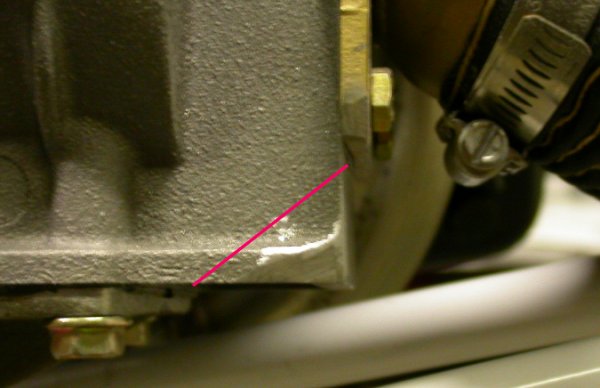 This pic shows how I'd recommend trimming off a bunch of excess material
before mounting the SC. Apparently some superchargers came with this
(and the inlet plate corners) already trimmed, as shown in the pic Randy
Crothers sent me.
This pic shows how I'd recommend trimming off a bunch of excess material
before mounting the SC. Apparently some superchargers came with this
(and the inlet plate corners) already trimmed, as shown in the pic Randy
Crothers sent me.
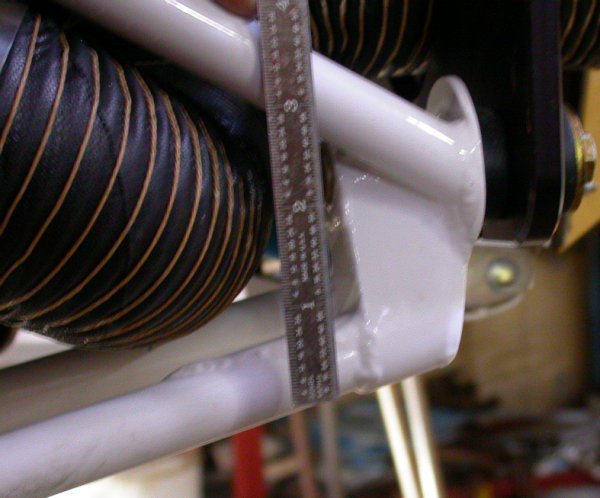 This pic shows in detail how much the lower RT frame tubes drop below the
bolt. Randy (and possibly others) is having a big problem getting his
SC to fit, because his engine mount does not have this drop. So, he
has no room to mount the SC and no room to get his duct onto the SC inlet.
This pic shows in detail how much the lower RT frame tubes drop below the
bolt. Randy (and possibly others) is having a big problem getting his
SC to fit, because his engine mount does not have this drop. So, he
has no room to mount the SC and no room to get his duct onto the SC inlet.
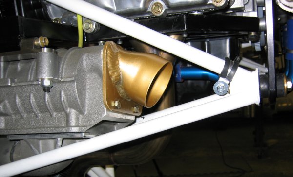 This is
a pic of Randy's frame for the same supercharged STi engine for RV-7A as me.
There is no drop in the fwd part of the 2 lower tubes; hence the
interference problems he's having. Note also that his SC inlet has had
the corners rounded before being anodized, and that the lower front part of
his SC came trimmed, as I'd previously recommended after seeing mine.
He got his engine before me, as did Carsten. Carsten's is like mine,
though. There's no way he's going to get
his SC inlet ducting on in there. I was barely able to get mine on,
and I have considerably more space to work in.
This is
a pic of Randy's frame for the same supercharged STi engine for RV-7A as me.
There is no drop in the fwd part of the 2 lower tubes; hence the
interference problems he's having. Note also that his SC inlet has had
the corners rounded before being anodized, and that the lower front part of
his SC came trimmed, as I'd previously recommended after seeing mine.
He got his engine before me, as did Carsten. Carsten's is like mine,
though. There's no way he's going to get
his SC inlet ducting on in there. I was barely able to get mine on,
and I have considerably more space to work in.
If you have a frame like Randy's, you will have to modify the SC inlet and outlet extensively to get it to fit. I'd have thought it'd be easier to replace the frame, but this is how Randy did it:
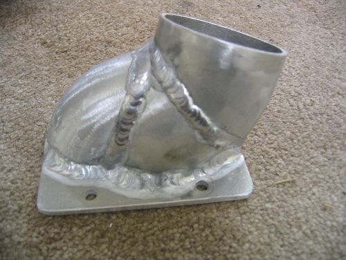 Randy's inlet tube, extensively modified.
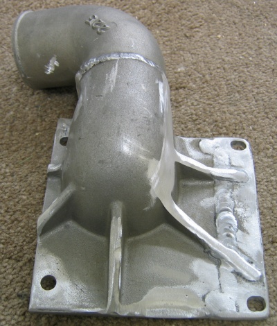 Randy's supercharger outlet, extensively modified. Randy had to cut
about an inch off one side of the mounting plate and move everything over.
Randy's supercharger outlet, extensively modified. Randy had to cut
about an inch off one side of the mounting plate and move everything over.
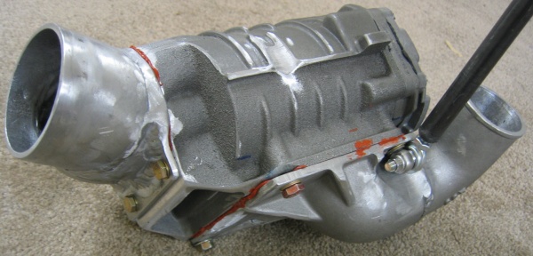 Randy's extensively modified supercharger, ready to put in the plane.
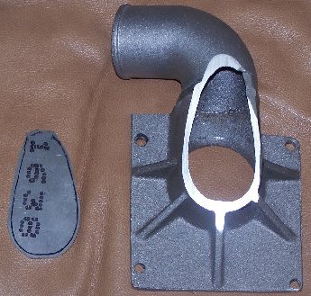 This pic shows how Jan had recommended dealing with more interference than
what I had on the SC outlet. Cut the big hole and weld the plate over
it.
This pic shows how Jan had recommended dealing with more interference than
what I had on the SC outlet. Cut the big hole and weld the plate over
it.
Dec 24 - worked all day on cleaning up garage, tools, and an old "temporary" bench I started piling stuff onto about 13 years ago.
Dec 27 - Attempt to torque RT header nuts. No way will the 17mm crowfoot socket I bought work in there. Turned down a 17mm socket on the lathe and got the minimum wall thickness down from 0.070" to 0.045". Then got socket on OK. Used a universal joint with the turned-down socket, and set torque on RT header nuts to 25 ft lb. Removed LT header nuts and drilled safety wire holes in them. Torqued and safetied all header nuts. Access in there is getting tighter all the time. It was rather difficult to do the safetying. It was about the worst safetying job I've ever done, but I guess it's marginally OK. It's certainly better than the rest of the Eggenfellner engines (no safetying at all). Drilled and safetied the oil drain plug. Reinstalled RT oxygen sensor. Worked to 0330 making a bushing on the lathe, to use to hold an Adel clamp for the oxygen sensor cable onto an unused boss on the inboard side of the supercharger. Update web site 5.5 hr + 1.0 hr doc
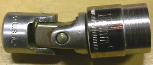 Here is the 17mm Craftsman socket I turned down on the lathe, so it would
fit on the RT inboard header stud nut. It was always a close fit in
there, and the new SC mount bracket seems to end up with slightly less
clearance. I reduced the diameter by about 0.050". I then measured the
exact wall thickness at each of the 12 points in the socket, and marked the
one that was a few thousandths thinner with the little red engraved mark.
Then I needed a universal joint to get it onto the nut with a ratchet.
Here is the 17mm Craftsman socket I turned down on the lathe, so it would
fit on the RT inboard header stud nut. It was always a close fit in
there, and the new SC mount bracket seems to end up with slightly less
clearance. I reduced the diameter by about 0.050". I then measured the
exact wall thickness at each of the 12 points in the socket, and marked the
one that was a few thousandths thinner with the little red engraved mark.
Then I needed a universal joint to get it onto the nut with a ratchet.
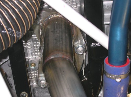 Here's the RT header safetied. The inboard nut is safetied to a hole I
drilled in the supercharger mount frame before I installed it.
Here's the RT header safetied. The inboard nut is safetied to a hole I
drilled in the supercharger mount frame before I installed it.
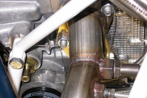 LT
header safetied. The safety wire runs are not quite as taut as they
should be, but they'll do the job. Safetying header nuts is always a
bitch of a job, because of tight access; worse here than on my race bikes.
LT
header safetied. The safety wire runs are not quite as taut as they
should be, but they'll do the job. Safetying header nuts is always a
bitch of a job, because of tight access; worse here than on my race bikes.
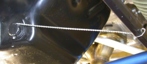 Oil
drain safetied. I drilled a hole in the aluminum frame fwd of the oil
pan to safety the plug to.
Oil
drain safetied. I drilled a hole in the aluminum frame fwd of the oil
pan to safety the plug to.
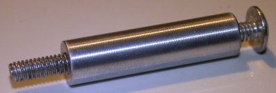 There is a large unused drilled boss on the inboard side of the
supercharger. It's a perfect place to mount an Adel clamp to secure
the oxygen sensor wiring coming off the RT header. Only problem is
that it has about a 0.350" ID hole in it; about the same size as the head of
the 8R30 screw I plan to use to secure the Adel clamp. So, I made a
bushing to go in there and fill up the space between the boss and the screw.
The bushing is 0.348" OD, 0.162" ID, 1.380" long.
There is a large unused drilled boss on the inboard side of the
supercharger. It's a perfect place to mount an Adel clamp to secure
the oxygen sensor wiring coming off the RT header. Only problem is
that it has about a 0.350" ID hole in it; about the same size as the head of
the 8R30 screw I plan to use to secure the Adel clamp. So, I made a
bushing to go in there and fill up the space between the boss and the screw.
The bushing is 0.348" OD, 0.162" ID, 1.380" long.
Dec 28 - Put away Wicks order of hardware, mainly for mounting Adel clamps. Install Adel clamp for oxygen sensor cable. Install Adel clamp to support coolant line. I was using all-metal locknuts, but the extra force required to tighten them was causing my screwdriver to strip the screw heads, so I switched to nylon locknuts. Safetied oil filter. Cleaned up workbench and finally finished cleaning the junk off my "temporary" bench on the west side of the garage. That project has taken years. Started working on muffler install. I decided to first replace the muffler fiberglass packing with stainless steel wool. I took one muffler apart, then decided to keep what I have, until it wears out. So, I put it back together. Update web site 5.5 hr + 1.0 hr doc
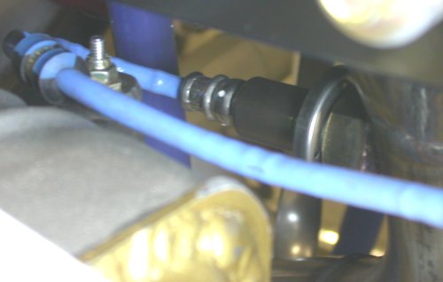 Here
is the oxygen sensor on the RT header, and the Adel clamp attached to the
mounting boss on the inboard side of the supercharger.
Here
is the oxygen sensor on the RT header, and the Adel clamp attached to the
mounting boss on the inboard side of the supercharger.
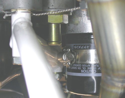 Here is the oil filter safetied. At the top of the pic, you can see
the LT inboard header nut safetied. There are 2 ways we use in racing
to safety an oil filter. You can put a hose clamp onto the filter,
then run safety wire through the screw housing to a solid point.
Sometimes, as here, we can just put the hose clamp on in such a manner that
the screw housing itself butts up against something. Here, the hose
clamp around the oil filter is put on so it is up against the engine frame
extension. This will prevent it from being able to loosen.
Here is the oil filter safetied. At the top of the pic, you can see
the LT inboard header nut safetied. There are 2 ways we use in racing
to safety an oil filter. You can put a hose clamp onto the filter,
then run safety wire through the screw housing to a solid point.
Sometimes, as here, we can just put the hose clamp on in such a manner that
the screw housing itself butts up against something. Here, the hose
clamp around the oil filter is put on so it is up against the engine frame
extension. This will prevent it from being able to loosen.
Sent Jan some questions about the mufflers & installation:
Q: First, I understand from previous emails on the subject that
the muffler clamps are not supposed to be very tight, or they will break;
they are there just to hold the locating pin. This is certainly contrary to
standard automotive (or motorcycle) exhaust practice, where the joints must
be crushed by the clamps to a gas tight fit, or they will leak heat and
noise. This isn’t a problem for those using the SuperTrapp mufflers? Isn’t
the inevitable exhaust leak there going to burn my cowl and/or paint and
increase noise?
A: Aircraft normally have slip joins all over the exhaust
system. This one has only one. The system is should be serviceable, not
crushed.
Q: Is the torque on the muffler clamps set to 50 inch pounds,
same as for similar clamps used in the supercharger to intercooler plumbing?
A: No, the clamp is only tight enough to prevent it and the
locking rivet from moving.
Q: Second, my mufflers are currently (without any cutting &
rewelding on the headers) quite close to the fuselage bottom skin, even when
just “hanging down” supported only by the headers (as I understand they are
supposed to be). My LT has a 5/16” gap from the top of the aft tip of the
muffler to the skin and the RT is 5/8”. I am concerned about heat and noise
being transmitted to the cabin floor with the mufflers so close. Is there a
minimum recommended gap between the top of the SuperTrapp case and the
fuselage skin?
A: If you can get them to 3/8 you are fine considering the
airflow in this area.
Q: Third, an earlier email (I think it was from Gary) said the
Lord mounts are not actually used to support the weight of the mufflers, but
more just to locate them. This again is contrary to what I know about auto
exhaust, where each component must have its weight supported by hangers. If
the weight of the mufflers is hanging off the end of the headers, it seems
inevitable to me that they will crack the headers. It seems to me that, at
the very least, the Lord mounts need to support at least some, if not all,
of the weight of the mufflers. What is the max muffler weight each Lord
mount should support?
A: The Lord mounts support the entire weight of the muffler and
is on muffler CG. The tailpipes only provide directional stability.
Dec 29 - Received my Accusump. Posted questions on Eggenfellner list about muffler mounting, heater plumbing, and other issues. Sent email to Jan about heater hookup plan. Found out I can't use Accusump in engine compartment - Accusumps cannot be installed in any place that might get hot, "especially not in a place where they will absorb heat after the engine is shut off". So much for that great idea. I guess I could mount it behind the baggage compartment, but I am not at all comfortable with running oil lines way back there. Requested a refund on the Accusump. Analyzed alternate Accusump mounting locations. Installed all heater plumbing. Reinstalled & plumbed Moroso coolant reservoir tank, using 1/4" polyurethane tubing as shock mounts and to take up the uneven mounting surface. Put together orders for more installation parts I'll need. Update web site. 5.5 hr + 0.75 hr doc
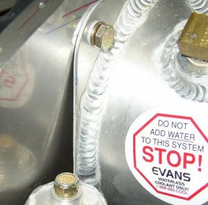 This pic, from earlier work, shows that the Moroso coolant tank cannot mount
flush to the firewall, due to the angle of the firewall top. I had
previously messed around with all sorts of ideas on how to deal with this.
This pic, from earlier work, shows that the Moroso coolant tank cannot mount
flush to the firewall, due to the angle of the firewall top. I had
previously messed around with all sorts of ideas on how to deal with this.
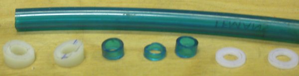 I had previously tried to use the white hard plastic bushings to deal with
the different angles of the coolant tank mounting hardware. I
had a brainstorm tonight, and just cut off pieces of 1/4" quite flexible
polyurethane fuel line to use as spacers for the 3 mounting bolts; 3/16"
long on
the top 2 and 9/16" long on the bottom one. The flexible nature of the
tubing will take up the slack in the angle between the coolant tank backing
plate and the firewall. It will firmly mount the tank, without
distorting the firewall.
I had previously tried to use the white hard plastic bushings to deal with
the different angles of the coolant tank mounting hardware. I
had a brainstorm tonight, and just cut off pieces of 1/4" quite flexible
polyurethane fuel line to use as spacers for the 3 mounting bolts; 3/16"
long on
the top 2 and 9/16" long on the bottom one. The flexible nature of the
tubing will take up the slack in the angle between the coolant tank backing
plate and the firewall. It will firmly mount the tank, without
distorting the firewall.
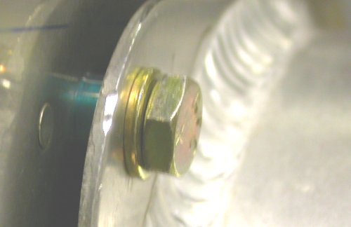 This shows how I used the little pieces of polyurethane fuel hose to make
a non-rigid mount for the coolant tank; one that will absorb the angle
differences. It seems to work great!
This shows how I used the little pieces of polyurethane fuel hose to make
a non-rigid mount for the coolant tank; one that will absorb the angle
differences. It seems to work great!
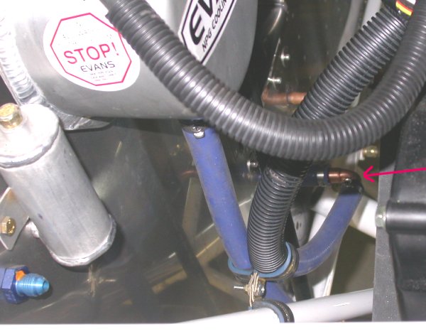 This pic shows some of the heater hoses installed. The red arrow
points to the little copper ell that Jim Skala made for me. He was
right; putting an ell there makes the installation MUCH better than trying
to bend the hose to go straight onto the heater fitting. The other heater fitting, the
copper thing further back in the background, is not yet plumbed in.
Boy, working with those Adel clamps sure is time-consuming! I
don't know why they're made of a spring material; seems something not as
springy would work as well and be a heck of a lot easier to install.
Doing 3 at a time, as shown here, is especially time-consuming I
had to exchange some emails with Jan to figure out the exact heater
plumbing. Confusion had been added by someone on the Eggenfellner list
(Gary?) talking about needing to use a tee in the system. No tee - I
just ran the heater hose from the top of the RT coolant tower to one heater
fitting, and hose #2 (from picture a few days ago) to the other fitting.
Quite simple. The hose #1 in the pic from a few days ago went to the
bottom of the coolant reservoir. I had to replace it with a longer
one, as it was too short to go under the SC-IC plumbing.
This pic shows some of the heater hoses installed. The red arrow
points to the little copper ell that Jim Skala made for me. He was
right; putting an ell there makes the installation MUCH better than trying
to bend the hose to go straight onto the heater fitting. The other heater fitting, the
copper thing further back in the background, is not yet plumbed in.
Boy, working with those Adel clamps sure is time-consuming! I
don't know why they're made of a spring material; seems something not as
springy would work as well and be a heck of a lot easier to install.
Doing 3 at a time, as shown here, is especially time-consuming I
had to exchange some emails with Jan to figure out the exact heater
plumbing. Confusion had been added by someone on the Eggenfellner list
(Gary?) talking about needing to use a tee in the system. No tee - I
just ran the heater hose from the top of the RT coolant tower to one heater
fitting, and hose #2 (from picture a few days ago) to the other fitting.
Quite simple. The hose #1 in the pic from a few days ago went to the
bottom of the coolant reservoir. I had to replace it with a longer
one, as it was too short to go under the SC-IC plumbing.
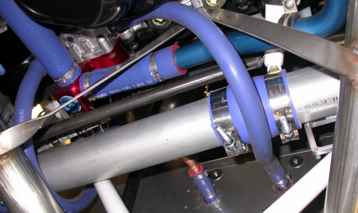 Here's a pic showing lots of detail for the heater hose installation.
The hose curving on the LT under the SC-IC duct goes from the outboard side
of the water pump to the bottom of the Moroso coolant tank. This hose
looks like it's close to the RT header pipe, but it isn't. The hose
curving under the SC-IC duct goes from the inboard side of the water pump to
the LT heater fitting. The lengths were chosen to make nice gentle
sweeping curves under the SC-IC duct without touching the duct. On the
RT heater fitting, you can see the 90 degree ell Jim Skala made for me.
That line goes to the coolant tower on the top RT of the engine.
These, as well as the SC-IC duct, will all be secured with Adel clamps
later, after I finalize the wastegate installation.
Here's a pic showing lots of detail for the heater hose installation.
The hose curving on the LT under the SC-IC duct goes from the outboard side
of the water pump to the bottom of the Moroso coolant tank. This hose
looks like it's close to the RT header pipe, but it isn't. The hose
curving under the SC-IC duct goes from the inboard side of the water pump to
the LT heater fitting. The lengths were chosen to make nice gentle
sweeping curves under the SC-IC duct without touching the duct. On the
RT heater fitting, you can see the 90 degree ell Jim Skala made for me.
That line goes to the coolant tower on the top RT of the engine.
These, as well as the SC-IC duct, will all be secured with Adel clamps
later, after I finalize the wastegate installation.
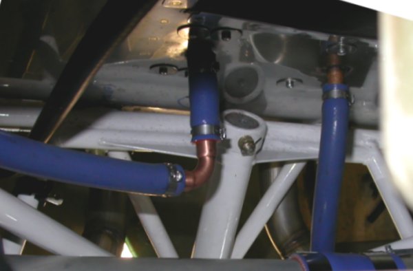 Here's a top view of the heater hose installation. Without the ell on
the RT heater fitting (LT in the pic), the hose to the fitting would be an awkward fit, and
would run closer to the spinning SC belt.
Here's a top view of the heater hose installation. Without the ell on
the RT heater fitting (LT in the pic), the hose to the fitting would be an awkward fit, and
would run closer to the spinning SC belt.
Dec 30 - posted questions for Eggenfellner list. Placed parts orders with Wicks (I no longer buy from Aircraft Spruce, unless absolutely necessary, due to their consistently poor customer service), MSC, McMaster-Carr. Posted questions about using oil line through cabin for Accusump. Hook up fuel pressure regulator. Dismantle wiring harness and work on getting it through the firewall. Update web site 3.0 hr + 0.5 hr doc
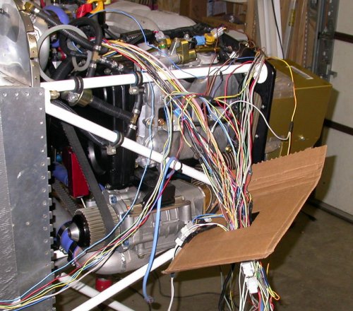 I used a piece of cardboard to make a test hole, to see how small a hole I
could make in the firewall and still get the wiring harness through it.
I started with 2.5" x 2", then 2" x 2", then decided to try round holes,
as they're easier to make. I ended up with a 2.125" round hole as about
the minimum practical size to use.
I used a piece of cardboard to make a test hole, to see how small a hole I
could make in the firewall and still get the wiring harness through it.
I started with 2.5" x 2", then 2" x 2", then decided to try round holes,
as they're easier to make. I ended up with a 2.125" round hole as about
the minimum practical size to use.
Dec 31 - Work to 0345 getting wiring harness through firewall and mounting Andair fuel filter. Plan mounting ECM. Plan mounting plumbing cross for fuel pressure switches. Install Andair firewall fuel filter. Update web site 3.75 hr + 1.0 hr doc
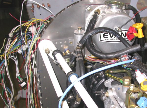 Here, I've got the wiring harness fed through the 2 1/8" hole I drilled in
the firewall. I was surprised at how easily the hole drilled, using a
hole saw. I had more problems free-hand drilling the holes in the intercooler
mount tabs than i did with this. I guess it was because, on the intercooler tabs, the soft aluminum allowed the pilot
hole to enlarge some during the drilling, so each hole ended up about 1/8"
larger than the hole saw. With the stainless steel, the drilling went
more smoothly than expected, and no enlargement of the pilot hole.
Here, I also have the coolant tank reinstalled (after removing it to install
the Gary Newsted low coolant level sensor), and the fuel pressure regulator
and related fuel lines are held firmly to the engine frame by several sets
of Adel clamps.
Here, I've got the wiring harness fed through the 2 1/8" hole I drilled in
the firewall. I was surprised at how easily the hole drilled, using a
hole saw. I had more problems free-hand drilling the holes in the intercooler
mount tabs than i did with this. I guess it was because, on the intercooler tabs, the soft aluminum allowed the pilot
hole to enlarge some during the drilling, so each hole ended up about 1/8"
larger than the hole saw. With the stainless steel, the drilling went
more smoothly than expected, and no enlargement of the pilot hole.
Here, I also have the coolant tank reinstalled (after removing it to install
the Gary Newsted low coolant level sensor), and the fuel pressure regulator
and related fuel lines are held firmly to the engine frame by several sets
of Adel clamps.
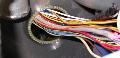 This is a closeup of the 2 1/8" hole through the firewall for the wiring
harness on the RT side. Note the temporary use of caterpillar tubing
around the hole, to avoid damaging the wires while feeding the harness
through the hole. Eventually, I will make a final grommeted and sealed
stainless steel plate to cover this hole, when the wiring is all done.
This is a closeup of the 2 1/8" hole through the firewall for the wiring
harness on the RT side. Note the temporary use of caterpillar tubing
around the hole, to avoid damaging the wires while feeding the harness
through the hole. Eventually, I will make a final grommeted and sealed
stainless steel plate to cover this hole, when the wiring is all done.
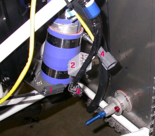 This shows the Andair firewall fuel filter installed. It also shows
the 4 LT connectors that need to be disconnected from the wiring harness, to
run the harness through the hole in the RT side of the firewall. The
wires for these 4 connectors will come back from the RT to the LT on the aft
side of the firewall, and will then come back through a smaller hole in the
LT side of the firewall to reconnect the 4 connectors.
This shows the Andair firewall fuel filter installed. It also shows
the 4 LT connectors that need to be disconnected from the wiring harness, to
run the harness through the hole in the RT side of the firewall. The
wires for these 4 connectors will come back from the RT to the LT on the aft
side of the firewall, and will then come back through a smaller hole in the
LT side of the firewall to reconnect the 4 connectors.
GO TO JANUARY, 2006 ENGINE PAGE
BACK TO MY RV BUILDER'S HOME
BACK TO BRIAN'S HOME