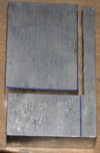
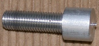
 Start with a chunk cut out of a block of 3/4" aluminum.....
ENGINE WORK July, 2005
July 1 - Clean up shop & update web site 0.5 + 2.5 hr doc
July 2 - more shop cleanup 2.0 hr
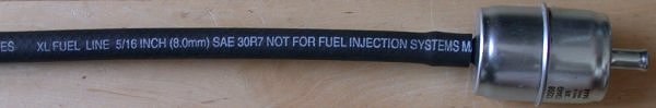
July 3 - more cleanup - it was quite a mess, with tools & parts scattered everywhere - and looking at what I'll need to order from ACS for the fuel pumps. The fuel pumps electric connections did not come with any nuts. It appears to be a 32 tpi thread; probably 8-32. All the plumbing is 5/16". I plan to swap out everything possible on the inlet side from the supplied 5/16" to 3/8". What I do on the pressure side will depend on what size Jan's Andair fuel filter is. If it's 5/16", then I'll leave things as they are. The fuel rail is 5/16", so going to 3/8" where possible may not be worth the effort. I've already gotten a couple 3/8" fuel filters for the inlet side of the pumps. With some forcing, they will go into the 5/16" hose into the pumps, and I'll plumb it back to the selector valve in 3/8". I'm still not too crazy about Jan's extensive use of rubber hose, and 5/16" at that, for the fuel lines. Part of the problem is that the pumps Jan supplies have 5/16" barbed hose fittings on each end. I don't know why Jan doesn't just use the pumps Van's supplies for Lycoming FI engines. Those pumps are designed for 3/8" metal fittings at both ends. Perhaps they don't flow enough gallons per hour; the Subaru engine, with its bypass fuel flow system, needs a high volume of fuel flow, as well as high pressure. 1.5 hr
July 5 - Planning for updating fuel pumps assembly. Swap small 5/16" pre-filters that came with it for larger 3/8" filters. Spent a hugely inordinate amount of time fabricating an aluminum wye fitting to split the line from the selector valve into the 2 pre-filters. Update web site 6.0 hr + 1.0 hr doc
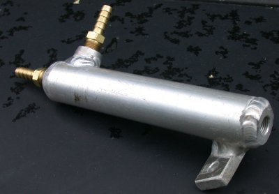
Start with a chunk cut out of a block of 3/4" aluminum.....
 ....and
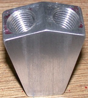
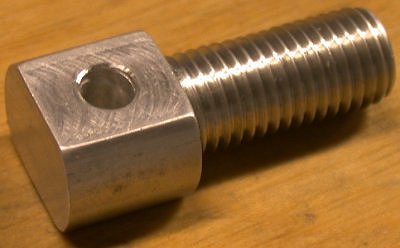
after WAY too many hours milling, drilling, tapping, etc, you have an
aluminum Y-block to send the fuel from the single Andair selector valve to
the 2 pump inlet pre-filters. The wye will give much more efficient
flow than using a tee.
....and
after WAY too many hours milling, drilling, tapping, etc, you have an
aluminum Y-block to send the fuel from the single Andair selector valve to
the 2 pump inlet pre-filters. The wye will give much more efficient
flow than using a tee.
July 6 - Got my reworked radiators back from Eggenfellner. No replacement Oetiker clamps included, as I'd requested and paid extra for. No Andair filter, as I'd ordered & paid for. They also have a new threaded port on them that I don't know what it's for. Emailed Jan about all these things. Also received the replacement PSRU vent bottle. The Oetiker clamp collection I ordered from Jan is not very complete. Some of the sizes he's using, like 22.6 (heater hose), 13.3 (PRSU vent tubing), are not in the kit. Also, how snug are these supposed to be before tightening? ACS only sells them in 1" and larger sizes. Updated web site. 3.0 hr + 1.25 hr doc
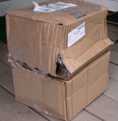 The box the reworked radiators came back in was all smashed up, but Jan
had used some bubble wrap with them, so they were safe.
The box the reworked radiators came back in was all smashed up, but Jan
had used some bubble wrap with them, so they were safe.
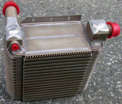 Here's one of the reworked radiators. You can see where they bored
into the fittings, then welded them back up. I don't yet know
what the small 1/8 NPT port has been added for. I emailed Jan about
it. Later found it had a plug in there that Jan forgot to send, so he
send them to me.
Here's one of the reworked radiators. You can see where they bored
into the fittings, then welded them back up. I don't yet know
what the small 1/8 NPT port has been added for. I emailed Jan about
it. Later found it had a plug in there that Jan forgot to send, so he
send them to me.
 Here's the new PSRU vent bottle. The bracket still has the big angle
on it, but it's welded on much higher on the bottle, so the top of the
bottle shouldn't interfere with the frame plate. I'm not sure what the
threaded port at the top is for. Later found out a pipe plug,
with a tiny vent hole drilled in it, is supposed to go in there. It
should have been included with the bottle, but it wasn't, so that was yet
another item to order for the complete FWF package.
Here's the new PSRU vent bottle. The bracket still has the big angle
on it, but it's welded on much higher on the bottle, so the top of the
bottle shouldn't interfere with the frame plate. I'm not sure what the
threaded port at the top is for. Later found out a pipe plug,
with a tiny vent hole drilled in it, is supposed to go in there. It
should have been included with the bottle, but it wasn't, so that was yet
another item to order for the complete FWF package.
July 7 - Exchanged some emails with Eggenfellner about the small 1/8 NPT fittings on each radiator. When I sent the radiators out, they were plugged. When I got the radiators back, they were open, so I asked Jan about it. He initially said they were for 2 water temp senders. Water temp?? I sure hope not, as it’s not a good reading to get water temp from the radiators. I had wondered about this previously, when Gary was talking about his engine not getting warm enough, and he needed to block off part of the radiator air intakes. If the engine is not hot enough, the thermostat is supposed to remain closed, allowing the engine to get hotter. With the thermostat closed, the water in the radiators will still have cooling air passing by them, and will get quite a bit cooler than the engine. But the engine in that case would be much warmer; that’s why we should not be reading water temp from the radiators- we should be reading it from a water jacket on the engine side of the thermostat. We don’t care what is the water temp in the radiators; we care what it is in the engine. If the air is quite cold, the thermostat will be closed much of the time, resulting in highly erroneous water temp readings. Anyway, Jan eventually corrected himself and said my senders are on the blue coolant towers at the top of the engine, and the 2 holes in the radiators should be plugged. He will send me the plugs. Worked on dismantling the fuel pumps assembly, so I can redo it in mostly 3/8". Also, Jan is using the much stiffer and more expensive fuel injection hose on the supply side of the pumps. There is no need for it there. I put together an order for some polyurethane hole from MSC that should work very nicely on the non-pressure side of the pumps. I also placed an order with ACS for plumbing parts. 0.25 hr
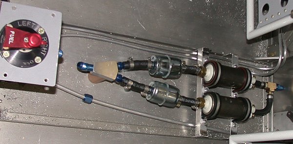
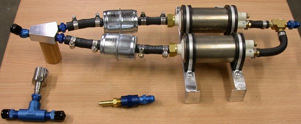
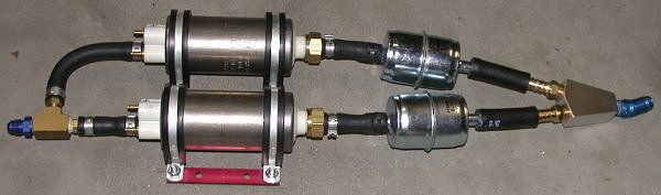 This
is a loosely-laid-out look at how I plan to redo the pumps, with solid
aluminum lines going out both sides. When I get my ACS order, I will
be redoing the pressure side (LT in pic) to 3/8", not the present 5/16".
This
is a loosely-laid-out look at how I plan to redo the pumps, with solid
aluminum lines going out both sides. When I get my ACS order, I will
be redoing the pressure side (LT in pic) to 3/8", not the present 5/16".
July 8 - Placed MSC order for hose, fittings, clamps, and a few other things. Found some small aluminum flakes in the reworked radiators and embedded in the red "protective" caps on the radiators. Blew out the radiators with compressed air. I should do that at least one more time, too. I also noted that some of the radiator rework welds look pretty sloppy (and cold) from the inside, but the outside looks like it will hold. Looking into how to mount the fuel pumps, and removed the 3/8" fuel supply line I'd installed much earlier. Also noted that the PSRU vent bottle now fits OK, but the supplied mounting screws are still too short, they have no washer, and the nuts supplied are plastic locknuts. So, I'll have to order longer screws and metal locknuts. Also, the holes in the PSRU vent bottle mount tab and the holes in the engine mount plate don't match up very well (distance apart). Avoiding all this chasing down, and repeatedly ordering, lots of small parts is supposedly one reason I paid for a FWF engine. I also went to the local auto parts stores to try to find some silicone heater hose. I finally found one store that had some silicone hose they were calling some sort of exhaust/emissions-related hose, and it was about $8 a foot. Since the heater hose supplied by Jan was defective, I called Jan to see if he'd send me what I need. He said he didn't feel the abraded jacket was a problem, but he said he'd send me some heater hose. He also mentioned that he'd figured out the reason he hadn't sent me my Andair filter was because he was out of stock on them. I think Jan is an honest guy, and he's trying to do a good job, but I don't think he's the most organized person in the world. He also said that the fuel pressure regulator I'd sent him was in fact the adjustable kind. I said I didn't see any adjustment, as described on the list. He said it's the same thing that the vacuum line from the manifold goes to. I sure wish that had been made clearer in the mail list conversations leading up to Jan suggesting I return the regulator. So, he's sending that back to me now. The idea of a smooth, complete, trouble-free firewall forward package is fading fast in the face of reality. Spent about an hour TIG welding a new frame to hold the fuel pumps to the floor angles. 4.25 hr
July 9 - more TIG welding on a frame to mount the fuel pumps to the floor aluminum reinforcing angles. Decided to remove the red pump frame supplied with the pumps. There had been zero deburring done on the red frame prior to anodizing it; quite rough edges, sharp edges, no washers under the nuts; apparently Jan doesn't believe in using washers? Because round head, rather than flat head, screws had been used in putting the pumps onto the red frame, it can't sit flat on something; it has to be mounted on spacers. The original plan was to make a frame to mount the red frame to. Now, I will just toss that red frame, and mount the pumps directly to my frame. I'm currently debating whether to mount the pumps on the frames as they are, so the brake and fuel return lines go UNDER the frame, or to cut the frame legs down some, and run the brake lines and fuel return line OVER the frame. If the frame is lower, the pumps will be a bit lower, and the frame will be a good place to put Adel clamps to secure the brake & fuel return lines. If the frame goes over the other lines, it will be far easier to remove the frame and pumps as a unit. I'm still pondering it. 5.0 hr
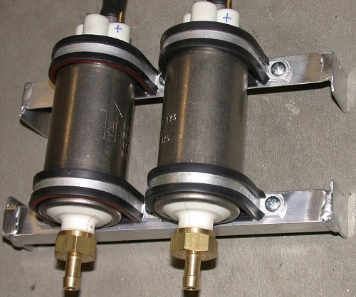 Here is the new fuel pumps frame. The tabs welded onto the ends of the
angle will bolt to the floor reinforcing angles. I have also taken off
the red frame from Eggenfellner, as well as the 5/16" FI hose supplied with
the pumps. I will replace the stiff FI hose with non-FI 5/16" hose, so
it'll easier to get 3/8" fuel filters into the hoses.
Here is the new fuel pumps frame. The tabs welded onto the ends of the
angle will bolt to the floor reinforcing angles. I have also taken off
the red frame from Eggenfellner, as well as the 5/16" FI hose supplied with
the pumps. I will replace the stiff FI hose with non-FI 5/16" hose, so
it'll easier to get 3/8" fuel filters into the hoses.
July 10 - put together yet another ACS order for screws, metal locknuts, nutplates. Spent some time putzing, planning, pondering mounting of fuel pumps assembly. I am also now thinking that perhaps using rubber hose from the 3/8" wye I made, back to the selector valve, may be better than using solid aluminum tubing; flex in the pre-filters area may weaken a solid connection to the selector valve. A rubber hose connection to the selector valve may be better to isolate any vibration. It may also make it easier to swap out the fuel pre-filters. I am also thinking of ways to secure the filters and wye, to minimize vibration and movement. 3.25 hr
July 11 - Ted Jerome, from TJ Imaging, came by to give me some tutoring in Photoshop. He's a consultant specializing in web design and Photoshop training. I spent a couple hours in the afternoon working with him on some basic techniques. I've been using an old copy of Paint Shop Pro. With some training and experience, I hope to get to use Photoshop more. It's a much higher end program than PSP. Received my MSC order of polyurethane tubing. What a major disappointment (and expense!) that was!! I have other 1/4" polyurethane tubing, and it is exceptionally flexible, so that's what I thought I was getting from MSC. This stuff is super-stiff. It's much stiffer than even the FI black rubber fuel hose. I can't use it at all, for this or most any other application. I bought a bunch of different sizes, and it's non-returnable. Grrrr! After looking into it more (after the fact), apparently polyurethane has different DUROMETER ratings, and all but the 1/8" stuff I just got from MSC is 95 durometer. The 1/8" is 85, and it's much more flexible. Wasted a bunch of time dealing with that, trying out various plumbing options, and putting together yet another MSC and ACS order. I had some ordinary, cheap non-FI 5/16" rubber fuel hose, and that worked much better than all the expensive, exotic hoses I bought. There's no need to use Fuel Injection hose on the non-pressurized side of the pumps. It's quite a bit more expensive, and it's much stiffer than non-FI hose. It's a real struggle to force a 3/8" fuel filter into the 5/16" FI hose, but no problem at all with the non-FI hose. WARNING: I had previously, at someone's suggestion, tried forcing the 3/8" fuel filter into the 5/16" FI hose. Later, after I decided to replace the 5/16" FI hose from the inlet side of the pumps, I realized that, when I'd forced the 3/8" fuel filters into the 5/16" FI hoses at the pumps, the sharp edge on the inside of the filter cut a little divot off the inside corner of the fuel hose. Had I not removed the 5/16" FI hose to replace with non FI hose, those little divots would have remained in the line between the pre-filters and the pumps. Not good. update web site 1.0 hr + 1.75 hr doc
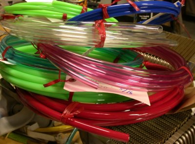 Here's a pic of all the polyurethane hose I bought, in different colors
and sizes. It wasn't as I expected, and I can't return it.
It's too stiff to be of much use anywhere.
Here's a pic of all the polyurethane hose I bought, in different colors
and sizes. It wasn't as I expected, and I can't return it.
It's too stiff to be of much use anywhere.
July 12 - put together yet another ACS and MSC orders. I went to the auto parts store and got some ordinary, cheap non-FI 5/16" rubber fuel hose. That worked much better than all the expensive, exotic hoses I bought. The 3/8" filter slipped into it without much problem. Received and put away an ACS order (AN fittings galore, hose clamps, and Adel clamps). Update web site some. 2.0 hr + 1.0 hr doc
 This shows the 3/8" fuel filter on the 5/16" non-FI hose. This
goes together and comes apart well enough to be usable.
This shows the 3/8" fuel filter on the 5/16" non-FI hose. This
goes together and comes apart well enough to be usable.
 This shows the fuel pumps temporarily installed in the cabin. The AN6
1/8 NPT pipe fitting I put on the end (replacing the supplied AN5 1/8 NPT
fitting) is right up against the firewall, so I ordered a 90 degree version,
along with a few other plumbing things, from Wicks.
This shows the fuel pumps temporarily installed in the cabin. The AN6
1/8 NPT pipe fitting I put on the end (replacing the supplied AN5 1/8 NPT
fitting) is right up against the firewall, so I ordered a 90 degree version,
along with a few other plumbing things, from Wicks.
July 13 - Sort out AN plumbing parts, start assembling plumbing parts for fuel pumps. Waiting now for my MSC order for Tygon. It is made specifically for fuel, and it has a durometer of 57, so it should be quite flexible and work well for what I want. Spent an hour or so on the phone with Chase Parkway Subaru and Bill at Eggenfellner. I got a 2004 STi manual from Parkway, but I thought Jan had said my engine was a 2005. All the numbers I could pull off the engine were not of much help in determining the exact year and model of my engine. They did determine that my ECM is a 2004 Forester, though. Bill is supposed to look into it further and get back to me. He never did. Dragged out my old Accusump and looked at how I might fit an Accusump in there. It looks like there is plenty of space under the LT side, right by the oil lines. The one I have is quite old. I got it back in the 70s and never used it. It's too big; 3 quarts. They make a nice 2 quart model now, though. I need to wait to order it until I get my supercharger, intercooler, etc, so I know what spare room I'll have. It's irritating to have to wait until October for stuff I was expecting to get with my engine last spring, but at least I'll have all the latest & greatest parts. At the end of the day, I got my MSC order with the Tygon. It works well, and it's very flexy. The 3/8" filter goes into the 5/16" Tygon without a lot of trouble, but the stretchiness of the Tygon makes it really grip the filter, and it's quite difficult to remove it. In fact, I had to cut it off the filter to get it off. So, I am back to the simple, local 5/16" non-FI hose I can easily get anywhere, rather than any of the exotic tubing types I tried. Assembled the fuel pumps & frame. 6.0 hr
July 14 - pondering more parts I'll need. I'll need to get an AN822-6-2D 90 degree 1/8 NPT to flare adapter to replace the straight AN816-6-2D at the end of my fuel pumps setup. The fwd end of the pumps assy will be right up against the firewall, so I'll need a 90 degree fitting to go up the firewall. I wondered if the fuel would flow back through the pumps when I remove the pre-filters for service, but people on the Eggie list said the pumps have a check valve in them. Laid out the fuel pumps in the cabin, and made a block out of hollowed-out closet rail to hold up the wye block I made. Experimented some with Shoe Goo and Automotive Goop, to see how well they work as isolators for parts or lines that come near each other. I had numerous questions for the Eggenfellner list. Included fuel pressure switch in my plumbing plans, continued assembling the plumbing for the fuel pumps. I found an unused threaded hole near the fuel rail that will be perfect for supporting the fuel line going to the fuel rail. I'll need to make something that will go in there and support an Adel clamp and 10-32 screw. The hole appears to be a 10 x 1.25mm thread. 2.5 hr
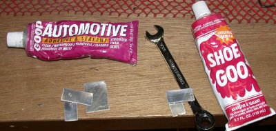 I experimented with Shoe Goo and Auto Goop, to see how good they are at
sticking to things, providing wear and vibration isolation, and resistance
to gasoline. It worked quite well for holding things apart
(isolation), but fell apart quickly when soaked in gasoline.
I experimented with Shoe Goo and Auto Goop, to see how good they are at
sticking to things, providing wear and vibration isolation, and resistance
to gasoline. It worked quite well for holding things apart
(isolation), but fell apart quickly when soaked in gasoline.
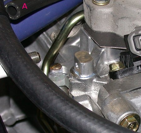
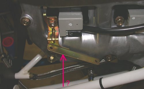
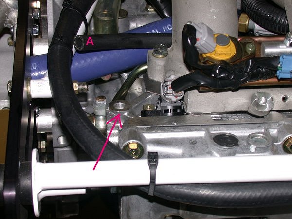 There is an unused threaded hole here at the arrow. It's a perfect
location for a junction from the 3/8" aluminum fuel tubing that will be
coming along the white frame, and transitioning to the 5/16" FI hose (A) to
the fuel rail.
There is an unused threaded hole here at the arrow. It's a perfect
location for a junction from the 3/8" aluminum fuel tubing that will be
coming along the white frame, and transitioning to the 5/16" FI hose (A) to
the fuel rail.
July 15 - Fabricated a threaded post from 5/8" round 6061T6 aluminum bar stock, to secure the fuel line at the fuel rail. Installed 5/16" FI hose at the fuel rail. Install 3/8" => 5/16" fuel rail transition at top of engine. Got some better FI clamps at auto parts store. Received my fuel pressure regulator back from Eggenfellner. Received yet another ACS order of small parts. Put away parts. Try to figure out how fuel regulator was mounted before I removed it. Start remounting headers. LT support bracket doesn't fit well. Tweaked it for a more relaxed fit. Installed PSRU vent bottle with proper hardware. Process pics & update web site. 6.0 hr + 1.75 hr doc
 I
made this "bolt" from 6061 T6 aluminum 5/8" round bar stock. The
thread is 10mm x 1.25mm for the threaded hole mentioned above.
I
made this "bolt" from 6061 T6 aluminum 5/8" round bar stock. The
thread is 10mm x 1.25mm for the threaded hole mentioned above.
 Here is the aluminum "bolt" completed. It will get screwed into the
threaded hole in the LT head, and the AN6 to 5/16" hose junction will be
clamped to that.
Here is the aluminum "bolt" completed. It will get screwed into the
threaded hole in the LT head, and the AN6 to 5/16" hose junction will be
clamped to that.
 Here are my fuel pumps, reassembled to my satisfaction, along with the
fittings for the AN6 to 5/16" junction to the fuel rail (bottom center) and
for the fuel pressure switch (lower LT). I am using a piece of
bored-out closet railing to support the plumbing wye I made. At the
far RT is the AN6 fitting with 1/8 NPT threads. The pumps came with
AN5 there, but I swapped it out for AN6.
Here are my fuel pumps, reassembled to my satisfaction, along with the
fittings for the AN6 to 5/16" junction to the fuel rail (bottom center) and
for the fuel pressure switch (lower LT). I am using a piece of
bored-out closet railing to support the plumbing wye I made. At the
far RT is the AN6 fitting with 1/8 NPT threads. The pumps came with
AN5 there, but I swapped it out for AN6.
 Here is the aforementioned aluminum bolt, screwed and loctited into place,
ready for the 5/16" FI hose (A) going to the fuel rail.
Here is the aforementioned aluminum bolt, screwed and loctited into place,
ready for the 5/16" FI hose (A) going to the fuel rail.
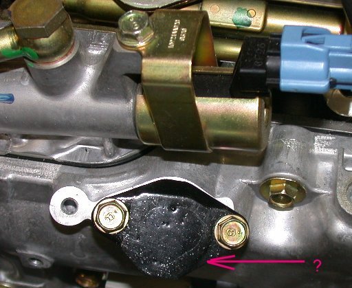
 I don't know what this bracket is. It looks quite extraneous to me.
I asked on the Eggie list about it, but didn't get any definitive answers.
I will be removing it. Jan subsequently said it's OK to toss this.
I don't know what this bracket is. It looks quite extraneous to me.
I asked on the Eggie list about it, but didn't get any definitive answers.
I will be removing it. Jan subsequently said it's OK to toss this.
 This
highly attractive gem is the oil filler cap.
This
highly attractive gem is the oil filler cap.
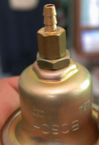 This is the fuel pressure regulator. Since there is no apparent
adjuster on it, and zip for instructions on things like this, Jan had me
return it, only to then tell me it already has an adjuster in it. I
finally got a decent explanation from Dick Tasker about how it works:
The barbed fitting has a hollow extension inside that
pushes onto the internal diaphragm, thereby effecting a fuel pressure
adjustment. When you are ready to set your fuel pressure you will loosen the
brass nipple and screw it out until your pressure is what you want. Then use
the locknut to lock everything in place.
This is the fuel pressure regulator. Since there is no apparent
adjuster on it, and zip for instructions on things like this, Jan had me
return it, only to then tell me it already has an adjuster in it. I
finally got a decent explanation from Dick Tasker about how it works:
The barbed fitting has a hollow extension inside that
pushes onto the internal diaphragm, thereby effecting a fuel pressure
adjustment. When you are ready to set your fuel pressure you will loosen the
brass nipple and screw it out until your pressure is what you want. Then use
the locknut to lock everything in place.
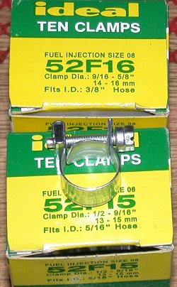 Here are
the new clamps I got at the local auto parts store. They are made
specifically for FI hose. They are better than the Breeze and AeroSeal
clamps I got from MSC and ACS. They are solid all the way around; no
slots to cut into the hose.
Here are
the new clamps I got at the local auto parts store. They are made
specifically for FI hose. They are better than the Breeze and AeroSeal
clamps I got from MSC and ACS. They are solid all the way around; no
slots to cut into the hose.
![]() Here is the completed fuel rail transition, at the LT side of the pic.
The AN6 3/8" aluminum fuel line will attach to that. On the RT side of
the pic, you can see where the 5/16" FI hose is on the fuel rail.
That's the LT fwd intake manifold port in the middle.
Here is the completed fuel rail transition, at the LT side of the pic.
The AN6 3/8" aluminum fuel line will attach to that. On the RT side of
the pic, you can see where the 5/16" FI hose is on the fuel rail.
That's the LT fwd intake manifold port in the middle.
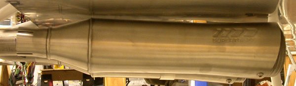
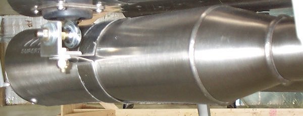
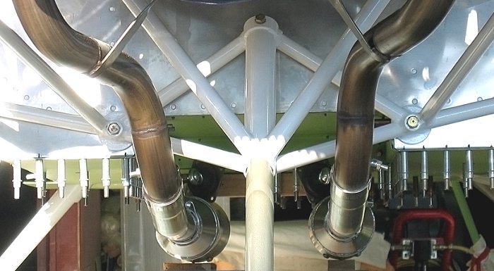
July 16 - Continued remounting headers. Found Jan's 6 x 30mm bolt for the header support braces was too long, and was hitting the case. I replaced it with a 6 x 22mm bolt. Loctited and tightened headers support bracket bolt. Tightened and torqued header bolts to 25 foot-pounds. I am concerned that there is no provision for safety wire or jam nuts on the exhaust stud nuts. That's SOP for racing. The studs appear to be 10 x 1.25mm, so I will try to find some nuts I can safety or some jam nuts. Started looking at mounting the mufflers. Grrrr! The instruction sheet that came with the mufflers says the drilled hole in the pipes is supposed to be on the TOP, which means I'd have to remove the headers I just installed in order to drill the holes. Noted very sloppy 1/4" rivet holes in muffler neck and inside the clamp - major burrs. The 1/4-28 nut on the clamps should be all-metal, not the nylon locknut. Also, the fit for the mufflers is so tight to the fuselage bottom skin that I can only slide the mufflers on upside down - with the seam pointing up. The hole Eggenfellner drilled in the muffler neck is also on the side with the seam, and the drawing shows the rivet hole on the top. It looks like the muffler will direct heat and noise at the bottom of the fuselage if installed this way. 1.25 hr
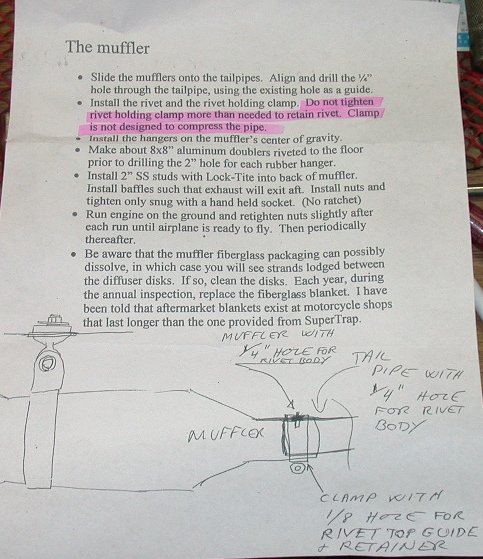 The mufflers came with this set of instructions. The hiliting is mine.
After much discussion on the Eggie list, the hole shown should be on the
BOTTOM. The muffler seam needs to go facing DOWN, so heat and noise
are not directed right at the bottom skin.
The mufflers came with this set of instructions. The hiliting is mine.
After much discussion on the Eggie list, the hole shown should be on the
BOTTOM. The muffler seam needs to go facing DOWN, so heat and noise
are not directed right at the bottom skin.
July 17 - Assembled mufflers and plates. All plates go in so the letters stamped on them are readable from the back. Posted questions on Eggie list about why muffler locating pin hole can't be on the bottom and why the seam is pictured as UP. Found out muffler seam should go DOWN, and locating pin hole can be anywhere. Tried to find some drilled 8-24 nuts for the muffler cap, but couldn't find any in ACS or Wicks. All are 8-32. Decided to drill out the supplied studs and nuts for safety wire. Finally got that done and the studs and nuts installed and safetied. Found I could get mufflers on by sliding on upside down, then rotating 180 degrees. Drilled 1/4" locator pin holes in header pipes. There is nowhere near enough room between the mufflers and fuselage skin to mount the mufflers as shown in the crude drawing supplied by Eggenfellner. Posted questions on Eggie list about how to deal with that. Gave up on mufflers and started reinstalling the reworked radiators. One of the radiator mount screws supplied by Eggenfellner (and red loctited into place) is too short. A lot of Eggenfellner's stuff seems to be more automotive-quality than aircraft-quality; what looks like hardware store fasteners, nylon locknuts in engine compartment, etc. Tried to remove the too-short screw, but I was afraid I'd break it off in the engine mount plate, so I used a miniature flanged nut there, and it seemed OK. 4.75 hr
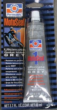 This is
from my second adhesive test. This stuff says it is gasoline
resistant. I was trying to find an RTV substitute that resists gas,
for isolating things from vibration or abrasion, where they can't be
clamped. This stuff, while probably a great gasket material, is
useless for that. It's very thin and runny. The Auto Goop has
worked about the best so far, with RTV doing very well, too, as long as
neither comes in contact with any gasoline.
This is
from my second adhesive test. This stuff says it is gasoline
resistant. I was trying to find an RTV substitute that resists gas,
for isolating things from vibration or abrasion, where they can't be
clamped. This stuff, while probably a great gasket material, is
useless for that. It's very thin and runny. The Auto Goop has
worked about the best so far, with RTV doing very well, too, as long as
neither comes in contact with any gasoline.
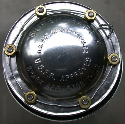 After I drilled all the nuts and studs, I safety wired them all together,
using 0.041" safety wire. The separate nuts & studs will be a big pain
to use in the future, because each nut, with a particular side facing out,
is unique to each stud. I exchanged some emails with SuperTrapp
customer support, and they are going to send me the "normal" Allen head cap
screws for the cap & plates. I'm not sure why these came with studs
and copper nuts for one muffler and brass nuts for the other muffler.
I had gotten some stainless steel wool for packing this, but I forgot about
it until I'd already secured the caps, so I'll just wait, until I have to
swap out the fiberglass blanket inside, to install the stainless steel wool.
After I drilled all the nuts and studs, I safety wired them all together,
using 0.041" safety wire. The separate nuts & studs will be a big pain
to use in the future, because each nut, with a particular side facing out,
is unique to each stud. I exchanged some emails with SuperTrapp
customer support, and they are going to send me the "normal" Allen head cap
screws for the cap & plates. I'm not sure why these came with studs
and copper nuts for one muffler and brass nuts for the other muffler.
I had gotten some stainless steel wool for packing this, but I forgot about
it until I'd already secured the caps, so I'll just wait, until I have to
swap out the fiberglass blanket inside, to install the stainless steel wool.
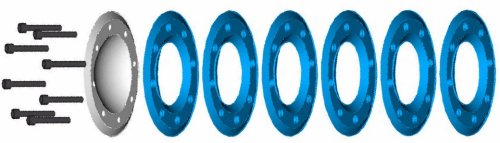 Here is a drawing I got from tech support at SuperTrapp, also showing the
proper orientation of the disks and end cap. The plates concave side
goes aft and the cap concave side goes fwd. Or, to put it another,
simpler way, the cap, and each plate inside, all are installed so that
you can read the words, stamped in each piece, from the rear.
Here is a drawing I got from tech support at SuperTrapp, also showing the
proper orientation of the disks and end cap. The plates concave side
goes aft and the cap concave side goes fwd. Or, to put it another,
simpler way, the cap, and each plate inside, all are installed so that
you can read the words, stamped in each piece, from the rear.
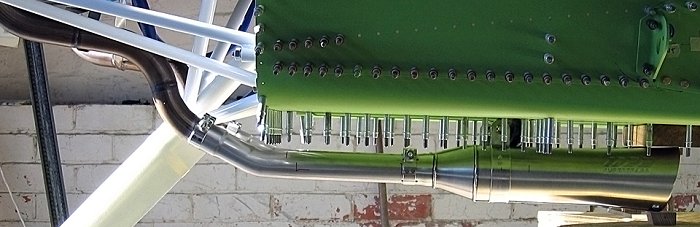
 The mufflers are only clearing the fuselage skin by a fraction of an inch,
even with the mufflers hanging all the way down at the bottom of their
vertical travel. There is NO WAY I can use Jan's supplied muffler
hanger bracket with the mufflers this close.
The mufflers are only clearing the fuselage skin by a fraction of an inch,
even with the mufflers hanging all the way down at the bottom of their
vertical travel. There is NO WAY I can use Jan's supplied muffler
hanger bracket with the mufflers this close.
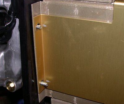 I guess Jan ran out of the proper length screws for the radiator & shroud
mounts in the middle of the job and just stuck something else in there.
The upper RT corner screw (upper LT in pic) is 3/4" and should be 7/8", like
all the others. There is no room for a washer here. The screws
are held in place through the engine mount plate with red loctite, so I was
afraid I'd break the screw trying to remove it and put the proper one back
in there. Sloppy stuff like this is not impressing me. Also,
while the REALLY critical stuff, like the engine mount bolts, seem to be
installed properly, with proper hardware, I am none too impressed with some
of the other things. Jan doesn't seem to believe in using washers in a
lot of cases. He's using nylon locknuts all over in the engine
compartment. He uses screws that are too short. I strongly
suspect that his hardware, like here and PSRU vent bottle mount, and Adel
clamp mounts, are all hardware store pieces, not aircraft quality.
They
look like hardware store screws & nuts. They're all silver colored.
All the cad plated aircraft hardware I've seen is a gold color.
I guess Jan ran out of the proper length screws for the radiator & shroud
mounts in the middle of the job and just stuck something else in there.
The upper RT corner screw (upper LT in pic) is 3/4" and should be 7/8", like
all the others. There is no room for a washer here. The screws
are held in place through the engine mount plate with red loctite, so I was
afraid I'd break the screw trying to remove it and put the proper one back
in there. Sloppy stuff like this is not impressing me. Also,
while the REALLY critical stuff, like the engine mount bolts, seem to be
installed properly, with proper hardware, I am none too impressed with some
of the other things. Jan doesn't seem to believe in using washers in a
lot of cases. He's using nylon locknuts all over in the engine
compartment. He uses screws that are too short. I strongly
suspect that his hardware, like here and PSRU vent bottle mount, and Adel
clamp mounts, are all hardware store pieces, not aircraft quality.
They
look like hardware store screws & nuts. They're all silver colored.
All the cad plated aircraft hardware I've seen is a gold color.
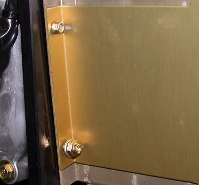 I ended up using one of these miniature 10-32 nuts with the built-in washer
here. This gave me barely enough thread projection after tightening.
Two of them came in my Van's kit,. so I'll need to replace them in my next
order. Note the all-metal locknut on the bottom. I am
replacing all Jan's (hardware store?) nylon locknuts in the engine
compartment with all-metal AN locknuts.
I ended up using one of these miniature 10-32 nuts with the built-in washer
here. This gave me barely enough thread projection after tightening.
Two of them came in my Van's kit,. so I'll need to replace them in my next
order. Note the all-metal locknut on the bottom. I am
replacing all Jan's (hardware store?) nylon locknuts in the engine
compartment with all-metal AN locknuts.
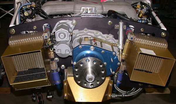 Here are the radiators reinstalled. I used Oetiker clamps on the 2
upper hoses, because of space (clamp width) restrictions as the hose goes
through the black plate. I used special lined hose clamps, made
specifically for silicone hose, on the lower hoses.
Here are the radiators reinstalled. I used Oetiker clamps on the 2
upper hoses, because of space (clamp width) restrictions as the hose goes
through the black plate. I used special lined hose clamps, made
specifically for silicone hose, on the lower hoses.
July 18 - Trying to figure out how to get my mufflers mounted. Robert Paisley suggested cutting the headers, bending them a bit, and welding the cut closed. I also thought of trying to mount the bracket on the SIDE of each muffler, thinking that a double-U type bracket, with 3 Lord mounts, would work well. Also got several private emails with pics of how others dealt with this problem. It had seemed to me that, if I mounted the bracket attach point on the SIDE of the muffler, I'd have to do it on EACH side of each muffler, so the muffler wouldn't try to rotate. Others are attaching to just one side of the muffler, and they say the locating pin keeps the muffler from trying to rotate. Update web site pics. 2.0 hr + 2.0 hr doc
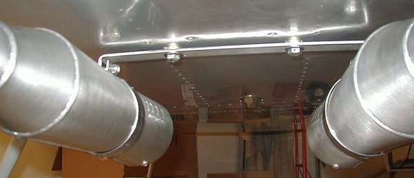
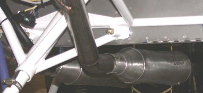 There's actually less clearance between the top of the muffler and the
fuselage skin than appears to be here, due to the reflection. After
exchanging some emails with the Eggie list, the suggestion from Robert
(haven't heard anything from Jan for awhile-maybe he's getting ready for OSH) was
to cut the header at the bottom bend, bend it down so there's enough
clearance to get the support brackets between the muffler and skin, and get
the header TIG welded back up. So now I get to pull the *&^%$#
headers again, as well as pull all the senders in the headers. It's
getting so the block and heads are about the only thing on this $%^&*!
engine that I have not had to rework myself or send back for rework. I
completely redid the entire fuel pumps assembly. So much for the
"complete FWF" concept. The only good thing is that I did get the new
style flywheel, damper, and PSRU. Guys like Carsten got the old
versions, so they will have to swap theirs out eventually. After
reading the manual for swapping out the PSRU, I am sure glad I don't have to
go through all that!
There's actually less clearance between the top of the muffler and the
fuselage skin than appears to be here, due to the reflection. After
exchanging some emails with the Eggie list, the suggestion from Robert
(haven't heard anything from Jan for awhile-maybe he's getting ready for OSH) was
to cut the header at the bottom bend, bend it down so there's enough
clearance to get the support brackets between the muffler and skin, and get
the header TIG welded back up. So now I get to pull the *&^%$#
headers again, as well as pull all the senders in the headers. It's
getting so the block and heads are about the only thing on this $%^&*!
engine that I have not had to rework myself or send back for rework. I
completely redid the entire fuel pumps assembly. So much for the
"complete FWF" concept. The only good thing is that I did get the new
style flywheel, damper, and PSRU. Guys like Carsten got the old
versions, so they will have to swap theirs out eventually. After
reading the manual for swapping out the PSRU, I am sure glad I don't have to
go through all that!
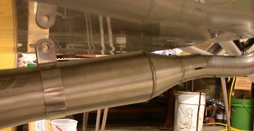 To cut the pipe and bend it so the mufflers will mount using the supplied
brackets will require a 15 degree cut, and result in this ugly mess.
The back of the muffler is 3" below the skin in this configuration, and the
angle looks lousy.
To cut the pipe and bend it so the mufflers will mount using the supplied
brackets will require a 15 degree cut, and result in this ugly mess.
The back of the muffler is 3" below the skin in this configuration, and the
angle looks lousy.
July 19 - spend time on Eggenfellner list, asking questions about all the headers, mufflers, and other problems. Update web site pics. 1.0 hr + 1.0 hr doc
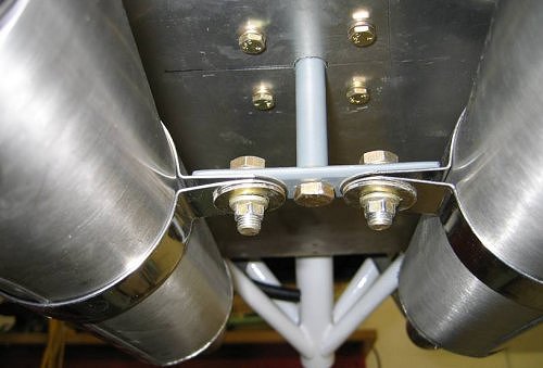
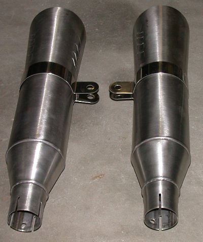 Here
are the mufflers laid out on the floor as they would go in the plane.
I am thinking of making a double-U bracket that supports from the middle and
2 outsides to replace the 2 clamps that support from the top center.
This will let me use the mufflers as they are on the headers. I also
spent quite a bit of time on the Eggie list, discussing the options to fix
this. Apparently both Mickey Coggins and Tom Moore had problems
with the mufflers being too low and far apart, so it looks like Jan went too
far the other way. ITMT, I am wondering if the mufflers being so close
to the fuselage bottom skin will put too much heat and sound into the
fuselage.
Here
are the mufflers laid out on the floor as they would go in the plane.
I am thinking of making a double-U bracket that supports from the middle and
2 outsides to replace the 2 clamps that support from the top center.
This will let me use the mufflers as they are on the headers. I also
spent quite a bit of time on the Eggie list, discussing the options to fix
this. Apparently both Mickey Coggins and Tom Moore had problems
with the mufflers being too low and far apart, so it looks like Jan went too
far the other way. ITMT, I am wondering if the mufflers being so close
to the fuselage bottom skin will put too much heat and sound into the
fuselage.
July 20 - unpack Wicks order, install AN822-6-2D 90 degree 1/4 NPT to AN6 adapter onto end of fuel pumps assmbly. Study pipes & mufflers problem some more. Ordered some stainless steel tubing from Burns Stainless Steel to fix the headers. Update web site pics. 1.0 hr + 1.0 hr doc
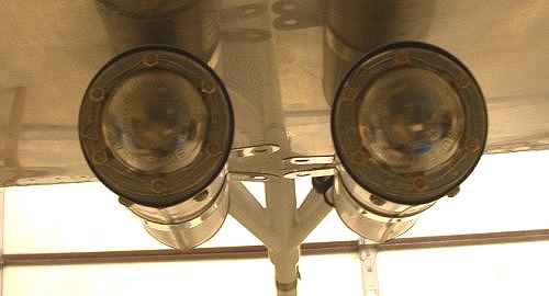 Here
are the 2 mufflers mounted as the header is configured now. I could
support the mufflers in the middle as here, with a plate between the 2
brackets and 2 more clamps (or, better, 1 double-U clamp supporting both
mufflers), with the mufflers as they are now. Mickey's mufflers
mounted with the RT lower than the LT, as shown here.
Here
are the 2 mufflers mounted as the header is configured now. I could
support the mufflers in the middle as here, with a plate between the 2
brackets and 2 more clamps (or, better, 1 double-U clamp supporting both
mufflers), with the mufflers as they are now. Mickey's mufflers
mounted with the RT lower than the LT, as shown here.
I got several private emails, each showing unique methods of hanging those mufflers. I guess I am not the only one with problems getting the mufflers to fit.
 Here's how Jake DeHaan did it on his RV9A with
a used 4 cyl Eggenfellner Subaru.
Here's how Jake DeHaan did it on his RV9A with
a used 4 cyl Eggenfellner Subaru.
 Here's how Larry Simpson did it for his H6-powered 7A.
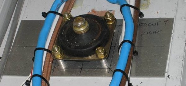 This is how Larry did his Lord mount ABOVE the skin surface, rather than
drill a big hole in the bottom skin for the rubber.
This is how Larry did his Lord mount ABOVE the skin surface, rather than
drill a big hole in the bottom skin for the rubber.
 Here's how Tom Moore did it. People, especially those with the widely
separated headers, are trying to mount them so the Lord Mounts are in the
center area, not further out in the area where pilot & passenger feet will
go. You can see how Tom accomplished that here. See Tom's H6 installation
website for more
Eggenfellner H6 engine installation details. Tom has also produced a
DVD on details of installing an Eggenfellner H6.
Here's how Tom Moore did it. People, especially those with the widely
separated headers, are trying to mount them so the Lord Mounts are in the
center area, not further out in the area where pilot & passenger feet will
go. You can see how Tom accomplished that here. See Tom's H6 installation
website for more
Eggenfellner H6 engine installation details. Tom has also produced a
DVD on details of installing an Eggenfellner H6.
 Here's a front view of John Moody's RV-8 muffler installation, from the
front.
Here's a front view of John Moody's RV-8 muffler installation, from the
front.
 This is John Moody's RV-8 muffler installation, from the side. Lots of
ways to skin this cat. I don't have nearly this much clearance between
the mufflers and the fuselage bottom skin.
This is John Moody's RV-8 muffler installation, from the side. Lots of
ways to skin this cat. I don't have nearly this much clearance between
the mufflers and the fuselage bottom skin.
July 21 - Jan finally returned to the list and had a flurry of answers to questions mostly already answered by the group. He replied to my continued queries about exactly what year and model my engine is by saying "Yes, you have a 2004 model engine as far as the manual is concerned and the ECU is a 2004 forester STI engine ECU." So, again, he still doesn't really say WHAT my engine is, he just claims that the 2004 STi manual will cover it. Also, there's no such thing as a Forester STi engine. It's one or the other. The Subaru dealer already told me my ECU is a 2004 Forester ECU, which is why I was asking exactly what model the engine is. As he did in January, Jan continues to tap dance around what exact model and year this engine is. He then sent me another of his nasty threat messages, in response to a sarcastic comment I'd made on the list about the head and block being about the only remaining engine components I haven't had to fix or swap out. He said he's "...sick and tired of my negative comments", and if I make one more, I will be kicked off the Eggenfellner mail list. I guess the last time I ignored his nasty threats, he figured I was someone who is accustomed to taking crap like that. And this is from a guy whose install manual is so out of date I recently started spending many plane-building hours updating it for free, just to help all Eggenfellner users. The whole company is so customer-driven. Gary Newsted did all his electrical design and the original manual for him. Robert Paisley has done all his STi development work. His presence at tradeshows is just customers and their planes. Anyway, I sent him a "brian-gram" in response.
July 22 - Updating the web page a bit from New Hampshire International Speedway. I haven't had time to update the web site, other than just dump in the captioned pics. I've been doing something on the engine-related work every day, though. I've also been busy updating the Eggenfellner Installation Manual, as a service for all Eggenfellner users. I'm leaving for OSH05 tomorrow, right after my race, so it'll be August before I do any more work on the plane. 1.0 hr doc
July 30 - Karla and I got back from OSH05 after a 12 hour, 875 mile drive Saturday from South Bend, IN. What a terrific show! It was all the usual great stuff; cool planes & related, cool cars, great seminars, loud air shows, etc. Plus I saw White Knight, SpaceShipOne, Global Flyer, Glacier Girl, presentations by Burt Rutan, Dick Rutan, Mike Melville, Brian Binney, Richard Branson, Paul Allen, Chuck Yeager, and much more one-of-a-kind stuff. The food seemed better than past years. I also visited the Eggenfellner booth, and met several other builders, including Tom Moore (H6), Mickey Coggins (STi), and Nathan Larson (single cam). Robert Paisley (supercharged, intercooled STI) was delayed, but he arrived eventually, and I took about 150 pictures of details of his STi engine installation, for my own info and for the Eggenfellner Installation Manual updates I am working on. I also visited the Innodyn turbine booth and drooled over their latest offerings, including a DUAL turbine under development. If I was not already committed to the Eggenfellner, I still might want to go Innodyn. However, it still (a year later) looks like I'd be Customer Number One. Supposedly, they have just signed a letter of intent with a new company to handle the FWF kit. The last FWF partner, Rivers Aeronautical, featured at OSH04, evaporated. I wish them well; it looks like a very cool engine if they get the FWF stuff figured out. It doesn't seem like it'd be that complicated, but maybe I don't know what I don't know.
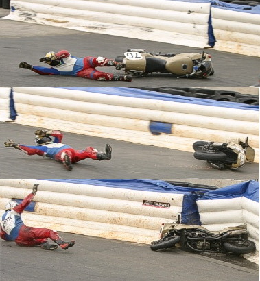
I was barely able to move at all last Sat & Sunday.
Last Saturday, I ran my race before leaving for Oshkosh, and crashed in the
first lap. That was OK, but then I was run over by 2 other bikes
running tight behind me. I laid in the track and couldn't move at all
at first, from wicked Charlie Horses on both legs where they'd been run
over, so I was taken in the ambulance to the Medical Center. After
getting out of the Medical Center, I headed out from the track about
6:30 PM, and drove 625 miles to Erie, PA in about 8 hours that night, then
another 625 miles in about 9 hours on Sunday to Oshkosh. As usual, the
Chicago mess was the worst part. I could barely walk at all,
especially Saturday and Sunday. I drove the first couple hours with an
ice bag on my legs, but it was so cold (ice directly on leg) that it was
making my leg painful from the ice. Each day was a bit better than the
day before. I had thought of renting a wheelchair there, but I ended
up getting by without one. It was especially difficult to squat down
at all. The legs still ache some, plus I still have aches and pains in
my knees, ankles, back, kidneys. I have massive black & blues on my thighs,
where I was run over. I am heading to the track again Wed night.
That was the second race in a row where I lost the front tire and crashed
while passing someone on the first lap. I guess it’s definitely time
for new tires on that race bike!
HERE is a triple pic someone got of
my crash in the June Production Twins race.
July 31 - received my stainless steel tubing
order from Burns Stainless.
Cut off some 1" long pieces to start practicing my stainless TIG welding, to
fix the headers so the mufflers will fit. I also did some stainless
TIG practice welding at the Lincoln booth at OSH, for the same reason.
I also picked up a copy of Tom Moore's Eggenfellner H6 Installation Video (for $50 -
should been included with engine) at OSH05, so I watched that. It
reminded me about the fuel pressure sender (as opposed to the fuel low
pressure warning/cutover switch), that I had forgotten to plan for in my
plumbing plans. It also answered a couple other questions for me.
Did more fuel plumbing layout & planning - added pressure sending unit.
2.5 hr
GO TO AUGUST, 2005 ENGINE PAGE
BACK TO MY RV BUILDER'S HOME
BACK TO BRIAN'S HOME