 Installed and adjusted the elevator Heim joints.
EMPENNAGE MOUNTING AND RIGGING - JULY, 2003
July 6, 2003 - Get out all the empennage pieces, find the empennage plans, lay the horizontal stabilizer in place, and look over the manual on how to attach the tail. I will start putting the tail onto the fuselage next week when I am home. 2.0 hr
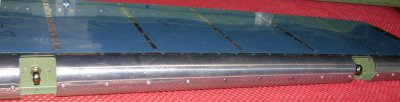
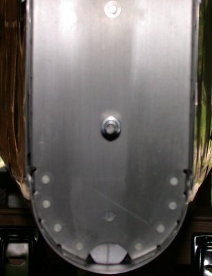
July 11 - Receive Finish Kit! Install Heim joints onto elevators. Make elevator temporary mounting pins. Mount elevators onto Horizontal Stabilizer. Make 1.020" spacer for drilling elevator horns. 6.0 hr
Installed and adjusted the elevator Heim joints.
 I
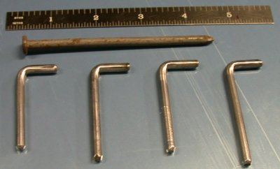
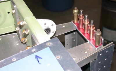
made these pins for temporarily mounting the elevators. I used big 20D
nails; cut the heads off, and turned the ends down on my lathe
for a perfect, snug fit in the Heim joints & brackets. They work well.
I
made these pins for temporarily mounting the elevators. I used big 20D
nails; cut the heads off, and turned the ends down on my lathe
for a perfect, snug fit in the Heim joints & brackets. They work well.
July 12 - Adjust elevator Heim joints more. Drill elevator horns for pushrod. Fit Horizontal Stabilizer to fuselage. Measure about 100 times to make sure tail is on square and centered before and after drilling. Drill HS-714 forward spar holes to fuselage. See my notes below about locating these critical outboard forward spar holes. 4.0 hr
 I'll need to trim away the skin where it interferes with the elevator
counterweight arms, but for now, it makes it very handy for holding the
elevators in trim position while I work on the adjusting and fitting.
I'll need to trim away the skin where it interferes with the elevator
counterweight arms, but for now, it makes it very handy for holding the
elevators in trim position while I work on the adjusting and fitting.
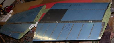 Elevators
mounted to Horizontal Stabilizer.
Elevators
mounted to Horizontal Stabilizer.
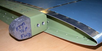
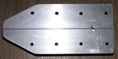
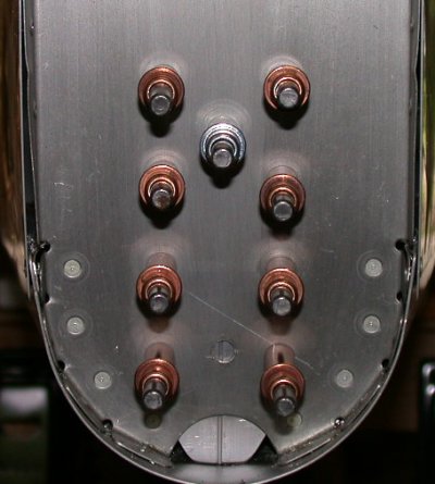
 I made
this block as per the plans for ensuring the hole drilled through the horns is
perfectly perpendicular to them.
I made
this block as per the plans for ensuring the hole drilled through the horns is
perfectly perpendicular to them.
 IMPORTANT NOTE: Locating the 2 outboard bolt holes for attaching the HS-714
Horizontal Stabilizer forward spar to the fuselage deck is critical.
The plans give 4 1/16" out from center for the inboard bolts.
Their ultra-precise location is not critical. Just get them the proper
distance out from center, and center them fwd-aft in the available leg of
the angle aluminum of the HS-714. The placement of the outboard bolts
is critical, though. You can see what I mean if you get a flashlight
and inspection mirror, and look underneath the fuselage rear deck to see
what you will be drilling through. As you will see, you are hitting 2
intersecting pieces of 1/8" aluminum angle under there; the side edge
of the longeron and the end of the F-710B angle that goes across between the
longeron on each side. If you are off (inboard/outboard-wise) by even
1/16", you will be too close to the edge of one angle or the
other. I figured all this out when I looked under there to see what I
was drilling.
IMPORTANT NOTE: Locating the 2 outboard bolt holes for attaching the HS-714
Horizontal Stabilizer forward spar to the fuselage deck is critical.
The plans give 4 1/16" out from center for the inboard bolts.
Their ultra-precise location is not critical. Just get them the proper
distance out from center, and center them fwd-aft in the available leg of
the angle aluminum of the HS-714. The placement of the outboard bolts
is critical, though. You can see what I mean if you get a flashlight
and inspection mirror, and look underneath the fuselage rear deck to see
what you will be drilling through. As you will see, you are hitting 2
intersecting pieces of 1/8" aluminum angle under there; the side edge
of the longeron and the end of the F-710B angle that goes across between the
longeron on each side. If you are off (inboard/outboard-wise) by even
1/16", you will be too close to the edge of one angle or the
other. I figured all this out when I looked under there to see what I
was drilling.
Don't go by the measurement in the plans; instead, make sure the spot you pick (left to right) is exactly centered between the end of the F-710B and the edge of the longeron. I did this by making the green line on the HS-714 that's in line with the center of the line of rivets going down through the longeron. Then I could see that line would place my hole a bit too close to the end of the F-710B, so I made a blue line by placing the rule along the inboard edge of the above-mentioned rivet heads. Then I center punched my drill point halfway between the 2 lines, and in the midpoint, fwd/aft-wise, of the HS-714. This hole ended up being as much as 1/8" inboard from the point I had determined by measuring 27/32", as per the plans, outboard from the inboard bolts. If I'd drilled it at 27/32" outboard, it would have been too close to the end of the F-710B.
If the F-710B wasn't made as long as possible (mine was part of QB kit), that just exacerbates the problem. So, if your kit isn't a Quick Build, make sure you make that F-710B as long as you possibly can and still get it to fit between the left and right longeron. I can't get a camera in there to show you, but if you look under the aft fuselage deck, you'll see what I mean.
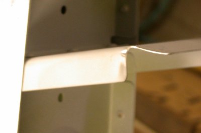
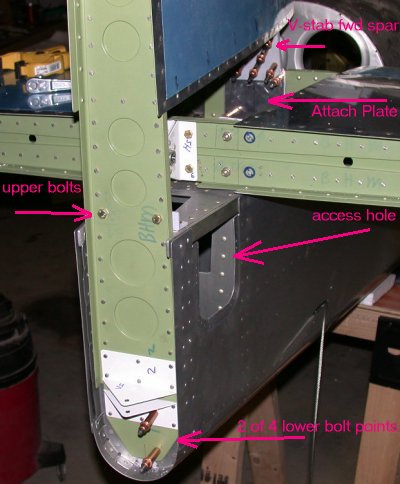
The pic also shows the F-798 shims in place. The unriveted hole on the left, with the red circle around it, will be drilled out to 3/16" and that's one of the 4 places the V-stab fwd spar gets bolted to the H-stab fwd spar.
July 13 - Resume mounting Horizontal Stabilizer after taking time out to put away Finish Kit. Make F-798 shims. Mount Horizontal Stabilizer; bolt forward spar to fuselage. Set H-stab incidence and check squareness yet again. Drill F-711C to HS-609 rear spar. Double check squareness after drilling. The son-of-a-bitch is now 1/8" out of square!! Jesus Christ! I can't believe this. I guess I'll write Van's & ask their advice. I think there's enough room to drill new holes. I checked it just before drilling. It was double-clamped, and I used a cleco after each hole; first 1/8" pilot holes, then #12 final holes. I guess it moved during drilling somehow. GRRRRR! The only other options are to let it slide or to enlarge the existing holes, but I don't like the sound of either of those two ideas. I guess next time, and my advice for anyone following this is to check it after drilling EACH 1/8" pilot hole and again after EACH final #12 hole (especially after each pilot hole). I think I'd also recommend using the swivel pad type all steel Vise-Grip C-clamps for clamping here, not the rubber pad clamps I used. The rubber pads protect the metal, but they also can squirm too much.
I haven't been logging my time to keep the web site up, but, as documentation of my work is part of the FAA requirements, and this is my documentation, as well as a guide for other builders and what is hopefully interesting reading for others, I am now going to start doing logging my documentation time. It also helps me keep track of what is increasingly seeming like a LOT of time spent keeping up the details on the web site; time that could be spent on working on the plane. 4.0 hr + 3.0 hr documentation
![]() Fabricated the
F-798 shims to go under the H-stab forward spar. The red is
machinist's dye for accurate marking (scratch marks show up very clearly,
and they are quite precise).
Fabricated the
F-798 shims to go under the H-stab forward spar. The red is
machinist's dye for accurate marking (scratch marks show up very clearly,
and they are quite precise).
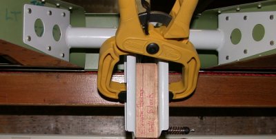
 This
shows how the Horizontal Stabilizer rear spar gets fastened and how the
incidence is set. The manual mentioned putting a drill bit under the
spar to hold it up, but I found that just using a piece of tapered wooden
shingle worked much easier, without fooling around with different drill bits
to get the height (H-stab incidence) set just right. This pic is
actually from my second attempt, after I found the H-stab was off a
bit. I was about to drill new holes, until Van's said not to try to
perfect it. The first time I did it, I used different drill bits until
I got the right height, which may have contributed to the incidence being
off by 0.1 degree. I think this way is much better, and I suggest it,
if you are following this procedure. Also see my July 20 notes
regarding H-stab incidence.
This
shows how the Horizontal Stabilizer rear spar gets fastened and how the
incidence is set. The manual mentioned putting a drill bit under the
spar to hold it up, but I found that just using a piece of tapered wooden
shingle worked much easier, without fooling around with different drill bits
to get the height (H-stab incidence) set just right. This pic is
actually from my second attempt, after I found the H-stab was off a
bit. I was about to drill new holes, until Van's said not to try to
perfect it. The first time I did it, I used different drill bits until
I got the right height, which may have contributed to the incidence being
off by 0.1 degree. I think this way is much better, and I suggest it,
if you are following this procedure. Also see my July 20 notes
regarding H-stab incidence.
 This
shows the V-stab mounted above the H-stab, and where I'll need to put in the
F-781 Vertical Stabilizer plate. I didn't see the F-781 on the plans at
first, but it was obvious it wasn't going to fit like this, so I looked
around and in my box of remaining fuselage parts, and found the F-781.
This
shows the V-stab mounted above the H-stab, and where I'll need to put in the
F-781 Vertical Stabilizer plate. I didn't see the F-781 on the plans at
first, but it was obvious it wasn't going to fit like this, so I looked
around and in my box of remaining fuselage parts, and found the F-781.
 This
shows how the forward spar gets trimmed. The plans say to trim
5/8" off the edges, presumably to allow for the bend I made. Gus
at Van's (in reply to my suggestion that this would have been a hell of a
lot easier if it had been part of the V-stab construction plans) said
This
shows how the forward spar gets trimmed. The plans say to trim
5/8" off the edges, presumably to allow for the bend I made. Gus
at Van's (in reply to my suggestion that this would have been a hell of a
lot easier if it had been part of the V-stab construction plans) said
OK, but I think that should probably be amended to "trim as necessary". Not everyone will need to trim 5/8 so it is better to leave it til the VS is installed to determine exactly how much to take off.
So, rather than just trim off 5/8", as I did, I guess you should trim it "as necessary". It didn't seem very important to me anyway, as all you're doing is bending it so it doesn't hit the Attach Plate.
 Aha! It's starting to look more like a real airplane, and less like an
aluminum boat.
Aha! It's starting to look more like a real airplane, and less like an
aluminum boat.
July 14 - Recheck incidence and squareness of Horizontal Stabilizer. Incidence is off by 0.1 degree and squareness is off by 1/16" at each tip. I removed the bolts and remeasured for new holes, while waiting for reply from Van's about this problem. Of course, 1/16" at the tips of the H-stab translates into only a few thousandths at the hole, but I want to get this perfectly right. So I carefully reset the H-stab where I wanted it and measured for new holes that would be exactly halfway between the edge of the current, centered, holes and the edges of the F-711C posts and HS-609 rear spar. It was 3/4", so centered at 3/8" will give me enough distance from a new hole to any edge or the original hole. Waited all day for a response to last night's email to Van's. Called them about it. Scott said don't worry about such a small difference; I won't notice it. Also, right after that, I got a reply from to my email question from last night. Gus said the same thing as Scott:
The best solution is to leave it alone. Odds are you can get a different measurement every time just depending on how much you pull on the tape. Even if accurate it is only .04% off, it won't affect the way it flies. Don't drill extra holes, they will weaken the bars too much and don't slot the holes as that may allow the HS to move.
So, even though it bothered me a lot to have it imperfect, from what Gus said, any attempts to perfect it will only make it worse (weaker), so I decided to leave it as is, reluctantly accept it as one more imperfection, and just move on. Good thing I didn't go ahead with my plan to drill new holes; I was just about to start doing that, when I got the reply.
Tried to fit Vertical Stabilizer. Lots of dicking around with that. It looks a lot easier to me to put the F-781 Attach Angle onto the V-stab first, then just mate it up where it fits to the forward spar of the H-stab. But the plans said to put it on the H-stab first, then fit the V-stab to that, so I am doing it that way. I also finally figured out that I need to fabricate the F-712D Up Elevator Stop first; that's what the top of the V-stab bolts to. Fabricated the F-712D Up Elevator Stop. LOTS of measuring and cutting for that piece; all 4 edges get different multiple measurements. Also had to write to Van's about exactly where this F-712D gets placed, because the plans don't specify. It seems like it should be flush at the rear, where the V-stab bolts to it, but the isometric drawing on Drawing 27A makes it look like it's forward of flush. Gus got back to me later and said it is flush at the aft edge. 8.0 hr
 Here is the Up Elevator
Stop after fabrication from 1.5" x 1" angle. Since both legs
of the finished angle were less than 1", I don't understand why they didn't just
make it from 1" angle. But I was a good boy and used the 1.5" x
1" like I was told. I'd sure hate to try to make stuff like this
without my handy horizontal/vertical metal bandsaw. Again, the red is
machinist's layout dye for marking.
Here is the Up Elevator
Stop after fabrication from 1.5" x 1" angle. Since both legs
of the finished angle were less than 1", I don't understand why they didn't just
make it from 1" angle. But I was a good boy and used the 1.5" x
1" like I was told. I'd sure hate to try to make stuff like this
without my handy horizontal/vertical metal bandsaw. Again, the red is
machinist's layout dye for marking.
July 18 - Mark, clamp, drill, cleco, debur, clean, and prime the F-721D Up Elevator Stop. 1.0 hr + 1.5 hr doc
 Here is the rear
view of the completed Up Elevator Stop clecoed into place, flush at the rear
edge. The V-stab gets bolted to the Stop's vertical leg. At the
upper left, you can see the ordinary, non-locking nuts I am using on the H-stab
rear spar for quicker and easier temporary mounting. They'll all be nylon
locknuts for final assembly.
Here is the rear
view of the completed Up Elevator Stop clecoed into place, flush at the rear
edge. The V-stab gets bolted to the Stop's vertical leg. At the
upper left, you can see the ordinary, non-locking nuts I am using on the H-stab
rear spar for quicker and easier temporary mounting. They'll all be nylon
locknuts for final assembly.
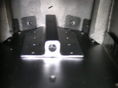
 Here is the front
view of the Up Elevator Stop, also showing (at the left side of the picture)
how the H-stab rear spar is bolted to the fuselage at those silver bars
coming up out of the fuselage. Gus also said the forward edge of the
Up Elevator Stop gets filed down later to set the exact amount of elevator
up travel. That's why its horizontal leg is cut 1/8" wider in
the center; to allow for trimming to fit. After priming, this will get
470-4 rivets in the 3 center holes and AN3 bolts in the outer 2 holes.
The orange on the 4 nuts in the middle of the H-stab rear spar show me those
4 bolts securing the elevator pivot bearing bracket have been
final-assembled and torqued. Also, note the gold clecoes on the ends
of the stop; you will need a few of these.
Here is the front
view of the Up Elevator Stop, also showing (at the left side of the picture)
how the H-stab rear spar is bolted to the fuselage at those silver bars
coming up out of the fuselage. Gus also said the forward edge of the
Up Elevator Stop gets filed down later to set the exact amount of elevator
up travel. That's why its horizontal leg is cut 1/8" wider in
the center; to allow for trimming to fit. After priming, this will get
470-4 rivets in the 3 center holes and AN3 bolts in the outer 2 holes.
The orange on the 4 nuts in the middle of the H-stab rear spar show me those
4 bolts securing the elevator pivot bearing bracket have been
final-assembled and torqued. Also, note the gold clecoes on the ends
of the stop; you will need a few of these.
July 19 - Primer on F-721D Up Elevator Stop was bad - peeling, so I removed the bad primer, cleaned it, and reprimed it. Riveted F-721D onto fuselage rear deck. Fabricated and primed F-712E rear tiedown. Attempt to dimple F-712A/B rear bulkhead, but it was too thick, so I countersunk it instead. Had quite a time placing tiedown and getting the fuselage rear bulkhead drilled to match it. Instead of making initial measurements to tiedown, as per the plans, and attempting to transfer those holes to the rear fuselage bulkhead by drilling from the front through a small hole, I should have marked the outline of the tiedown on the bulkhead and made the initial holes in the bulkhead, drilling from the rear. Got centerlines marked for fuselage and V-stab. Cleco and drill F-781 Attach Plate to H-stab fwd spar. Remount V-stab and set the 1/4" LT offset as per plans. Clamp V-stab in place. Cleco and drill F-781 Attach Plate to V-stab. 7.25 hr
 Shows where the rear
bulkhead came dimpled, so I had to countersink the rear tiedown where it mounts
behind this bulkhead. I put the tiedown behind this bulkhead and marked on
the tiedown centerline where this hole was located.
Shows where the rear
bulkhead came dimpled, so I had to countersink the rear tiedown where it mounts
behind this bulkhead. I put the tiedown behind this bulkhead and marked on
the tiedown centerline where this hole was located.
 This is the F-712E rear
tiedown. I drilled and countersunk it where it lined up with the dimpled
hole in the fuselage rear bulkhead. This extra hole ended up being the key
to me being able to mount this thing in place and get the 8 holes I made in it
transferred to the bulkhead.
This is the F-712E rear
tiedown. I drilled and countersunk it where it lined up with the dimpled
hole in the fuselage rear bulkhead. This extra hole ended up being the key
to me being able to mount this thing in place and get the 8 holes I made in it
transferred to the bulkhead.
 This is the
tiedown on the fwd side of the rear bulkhead. The only access in here was
though a small hole about big enough to get my hand into. It was very
tricky getting this picture.
This is the
tiedown on the fwd side of the rear bulkhead. The only access in here was
though a small hole about big enough to get my hand into. It was very
tricky getting this picture.
 This shows how
I was able to get the tiedown held in place. I drew a line down the center
of it, clecoed it in place through the dimpled hole, then was barely able to get
my angle drill into the forward side of this bulkhead and drilled through the
tiedown holes and out through the bulkhead. If you don't have an angle
drill and a good assortment of different length angle drill bits, this would be
impossible to drill from the front. A much smarter way would have
been to draw the tiedown outline here on the bulkhead, then lay out and drill
the 8 mount holes from THIS side.
This shows how
I was able to get the tiedown held in place. I drew a line down the center
of it, clecoed it in place through the dimpled hole, then was barely able to get
my angle drill into the forward side of this bulkhead and drilled through the
tiedown holes and out through the bulkhead. If you don't have an angle
drill and a good assortment of different length angle drill bits, this would be
impossible to drill from the front. A much smarter way would have
been to draw the tiedown outline here on the bulkhead, then lay out and drill
the 8 mount holes from THIS side.
 This is how it looked
after I got those 8 holes drilled through from the front, through a small
hole. 4 of these holes get flush rivets, and the other 4 are for what will
eventually be 3/16" holes for AN3 bolts to mount the V-stab. You can
also see that the bottom of the F-712E tiedown plate moved a bit to the left
during the drilling, and is no longer exactly centered, but it isn't critical.
This is how it looked
after I got those 8 holes drilled through from the front, through a small
hole. 4 of these holes get flush rivets, and the other 4 are for what will
eventually be 3/16" holes for AN3 bolts to mount the V-stab. You can
also see that the bottom of the F-712E tiedown plate moved a bit to the left
during the drilling, and is no longer exactly centered, but it isn't critical.
July 20 - Primed F-781 Attach Plate. With Karla's help, finished riveting and repriming the F-7115 Fuel Pump Cover. I may not need it, if I go for the Eggenfellner engine, but it was mostly finished, so I wanted to complete it while I had some help to hold it still while I riveted it. Cleco Attach Plate to V-stab, rehang V-stab one more time to make sure fit is still good. Remove V-stab and rivet Attach Plate to V-stab. Mount V-stab yet again and drill lower V-stab rear spar mount holes and H-stab forward spar to Attach Plate holes. Remove V-stab yet again and debur the (8) 3/16" mount homes. Mount V-stab again and bolt that puppy on. I must have had that V-stab on and off 20 times today, getting it just right. Hang elevators. Mark and drill elevator horns for hinge bearing. Even though I took great pains to mark the holes very accurately (using a 1/4" drill bit through the bearing), somehow in the hole enlargement (from 3/32" to 1/4"), the center of the holes ended up off from where I started. Very irritating. Will write Van's about best way to fix it. Set rudder rod ends, make 3 more temp mounting pins for rudder, and hang rudder. 4.75 hr + 3.0 hr doc
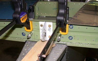
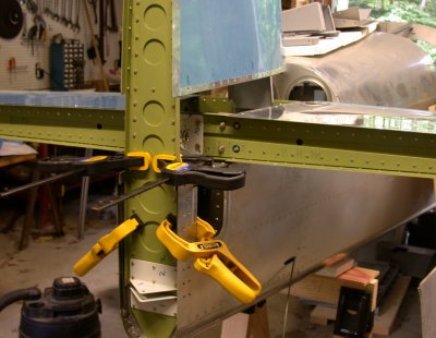 Initial V-stab clamping
into place
Initial V-stab clamping
into place
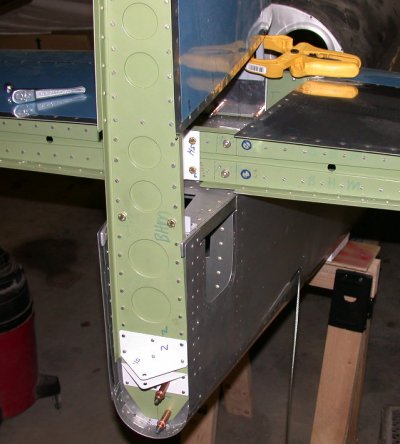 Center of pic shows 2 bolts in
place and a couple clecoes securing it at the bottom, while also clamping it at
the front. I used non-locking nuts for the bolts, because to get the
V-stab mounted right, it has to go on and off about a dozen times. First
you get the rear squared away, then the front is another multi-part
process. Also, when I did those rear spar mounts, I did it better than I
did on the H-stab. I got the V-stab perfectly perpendicular to the
H-stab. Then I drilled the left bolt hole you see in the center of the pic.
That caused it to move a bit, so it was off. I readjusted it to
perpendicular again. The plans said to then drill the right bolt head you
see. But I didn't do it that way, because trying to drill the relatively
larger 3/16" holes will cause some movement. Also, by the 2 bolts
being so close together, there is less leverage to keep the V-stab from wanting
to go to one side or the other. So, I next went down to
where you see the bottom cleco, and drilled a 1/8" pilot hole there.
Again, I had to do it from the front, through that little square hole you see up
higher on the
side of the fuselage, back-drilling through the holes in the tiedown, through
the fuselage rear bulkhead, and out through the V-stab. Again, that caused
some movement, but not as much, and it was with a 1/8" pilot hole, not a
3/16" final hole, so I could afford to then slot the 1/8" hole a
bit. So, with the drill bit spinning in the bottom hole, I pulled the top
of the V-stab sideways, to slot the 1/8" bottom hole some.
Then I remeasured again, and clecoed that hole. So, now I had it clamped pretty tight at 2 ends, so
then I drilled another 1/8" pilot hole above the first one (again, from the
front, though that little square hole you see. That time, it didn't move
at all, so I clecoed the upper pilot hole and went back up and made the second 3/16" hole where you see the
bolt head on the right. This let me then tighten up the bolts, and the
whole thing gradually got more and more rigid. I then made the other (2)
1/8" holes (for the 4 bottom mount bolts), backdrilling through the tiedown.
Then with 4 clecoes down there on the bottom (only 2 shown in this pic) it was
held tight, and I easily enlarged them to 3/16" from the rear. When I
was all done, the V-stab remained perfectly perpendicular.
Center of pic shows 2 bolts in
place and a couple clecoes securing it at the bottom, while also clamping it at
the front. I used non-locking nuts for the bolts, because to get the
V-stab mounted right, it has to go on and off about a dozen times. First
you get the rear squared away, then the front is another multi-part
process. Also, when I did those rear spar mounts, I did it better than I
did on the H-stab. I got the V-stab perfectly perpendicular to the
H-stab. Then I drilled the left bolt hole you see in the center of the pic.
That caused it to move a bit, so it was off. I readjusted it to
perpendicular again. The plans said to then drill the right bolt head you
see. But I didn't do it that way, because trying to drill the relatively
larger 3/16" holes will cause some movement. Also, by the 2 bolts
being so close together, there is less leverage to keep the V-stab from wanting
to go to one side or the other. So, I next went down to
where you see the bottom cleco, and drilled a 1/8" pilot hole there.
Again, I had to do it from the front, through that little square hole you see up
higher on the
side of the fuselage, back-drilling through the holes in the tiedown, through
the fuselage rear bulkhead, and out through the V-stab. Again, that caused
some movement, but not as much, and it was with a 1/8" pilot hole, not a
3/16" final hole, so I could afford to then slot the 1/8" hole a
bit. So, with the drill bit spinning in the bottom hole, I pulled the top
of the V-stab sideways, to slot the 1/8" bottom hole some.
Then I remeasured again, and clecoed that hole. So, now I had it clamped pretty tight at 2 ends, so
then I drilled another 1/8" pilot hole above the first one (again, from the
front, though that little square hole you see. That time, it didn't move
at all, so I clecoed the upper pilot hole and went back up and made the second 3/16" hole where you see the
bolt head on the right. This let me then tighten up the bolts, and the
whole thing gradually got more and more rigid. I then made the other (2)
1/8" holes (for the 4 bottom mount bolts), backdrilling through the tiedown.
Then with 4 clecoes down there on the bottom (only 2 shown in this pic) it was
held tight, and I easily enlarged them to 3/16" from the rear. When I
was all done, the V-stab remained perfectly perpendicular.
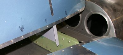
 This is a subsequent pic -
showing the drilling and clecoing tying the V-stab front spar to the H-stab
front spar through the Attach Plate. The leading edge of the V-stab gets
mounted 1/4" to the LT of center. The Attach Plate comes already
offset for this. I guess I primed and riveted the Attach Plate so
quickly I didn't get a picture of it.
This is a subsequent pic -
showing the drilling and clecoing tying the V-stab front spar to the H-stab
front spar through the Attach Plate. The leading edge of the V-stab gets
mounted 1/4" to the LT of center. The Attach Plate comes already
offset for this. I guess I primed and riveted the Attach Plate so
quickly I didn't get a picture of it.
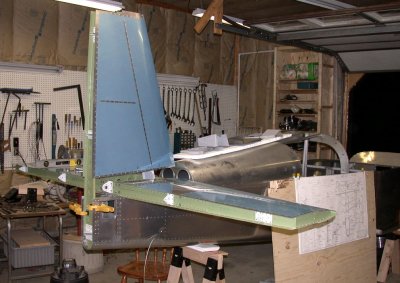
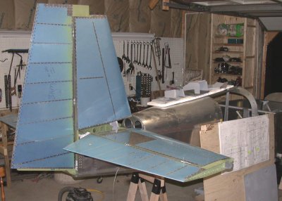 Here is the whole tail
mounted; Horizontal Stabilizer, elevators, vertical stabilizer, and
rudder. Next, I adjust the elevators and rudder.
Here is the whole tail
mounted; Horizontal Stabilizer, elevators, vertical stabilizer, and
rudder. Next, I adjust the elevators and rudder.
I got quite a scare when I
noticed that the 7A plans DWG 27A specify that the rear spar is supposed to be
3/16” above the fuselage rear deck. I
had already set my incidence by using a digital level (VERY handy tool-!)and
setting the H-stab so the tops of the H-stab front and rear spars were exactly
parallel with the tops of the longerons at the center of the cabin.
I got that method from the "From the Ground Up" video series I
watched, and I was under the impression that the 3/16” was an approximate
starting point. However, according to what I saw on the plans, it seemed to
just specifically set it at 3/16”. This
scared the hell out of me, because the bottom of my H-stab rear spar is
3/8” off the deck. I checked the
manual, and it said to check the height of the fwd and aft tooling holes on the
inboard H-stab ribs. So, I checked
the heights and they are exactly the same, so I am OK.
Whew!! Apparently, the 3/16" is in fact an approximate
starting point, but that's not what the wording on the plans indicates, so I was
quite worried there for awhile! I was going to double-check it with Van's,
but I try to minimize my queries to things that I am really stuck on, and I am
confident after having compared the height of the tooling holes that my
incidence is good.
July 21 - got an email back from Gus at Van's about my elevator horns and the holes for the hinge bearing. This is what he said:
It's possible the holes drifted off through multiple drilling with a handheld drill. It's probably better to drill these holes with a small bit through a bushing in the bearing and then enlarge them in one go. The best thing to do is either weld the holes closed, grind the surface smooth and redrill, or rivet on a piece of 4130 steel at least .040 thick over the holes and redrill through that. Don't enlarge the holes, if you do the elevator will be able to flex.
So, I guess I'll be getting out the MIG welder when I get back from OSH. I am working in MA this week, then going to AirVenture Friday for a week, so this will be my last entry for July.
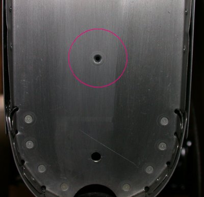
July 25 - Welded up the elevator horn holes and started grinding and filing them flat again. 3.0 hr
 No more hole.
GO TO AUGUST
BACK TO MY RV BUILDER'S HOME
BACK TO BRIAN'S HOME