 Here's the
drawing for this area; shows a pilot hole for the vent line and says 4 rivet
holes supposed to be left open.
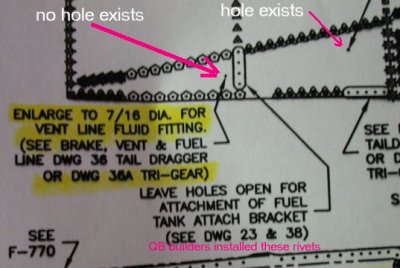
Here's the
drawing for this area; shows a pilot hole for the vent line and says 4 rivet
holes supposed to be left open.JUNE, 2003 fuselage work
June 1-3 - busy fixing problems on my computer. Reformatted & reinstalled everything.
June 4, 2003 - Study fuel line layout. Prime fuel valve bushings. Order FI fuel pump & gascolator from Van's. Drill out holes for fuel & vent lines. It all looks like a big complicated rat's nest in the drawing, but I guess if I just work on one piece at a time, it'll all come together. Spent much of the day on the phone and getting packed up to go do a contract on Long Island, NY. 2.0 hr
Here's the
drawing for this area; shows a pilot hole for the vent line and says 4 rivet
holes supposed to be left open.
 Well, as you can
see, there's no pilot hole, and all the rivets are already in place in the
QB kit. I wrote Van's, and they said drill out the 4 rivets and just
eyeball the location of the vent hole; its location isn't critical.
Well, as you can
see, there's no pilot hole, and all the rivets are already in place in the
QB kit. I wrote Van's, and they said drill out the 4 rivets and just
eyeball the location of the vent hole; its location isn't critical.
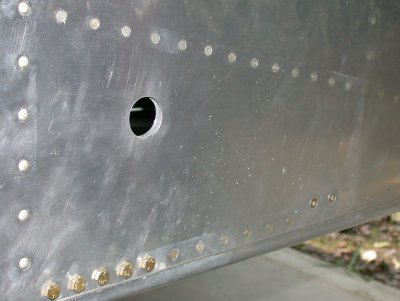 Drilled
& deburred the fuel line grommet holes (another place where the "both sides of a hole"
deburring blade is very handy, especially for getting the inside edge on
this double-walled hole).
Drilled
& deburred the fuel line grommet holes (another place where the "both sides of a hole"
deburring blade is very handy, especially for getting the inside edge on
this double-walled hole).
 Drilled
and deburred the holes for the fuel vent lines.
Drilled
and deburred the holes for the fuel vent lines.
June 9 - I'm back already from the job on Long Island. It was a pretty screwed up situation. Good to be home. Resumed fuel vent line layout. Drilled out excess rivets and put in grommets and snap bushings. Fabricated fuel vents from AN bulkhead fittings. 2.0 hr
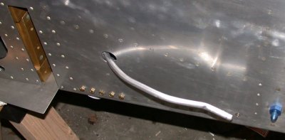
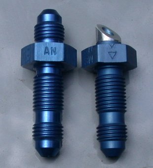 Before and after
pictures of making the fuel line vents from AN bulkhead fittings. Cut
the end off at 45 degrees and ground the threads off. These go at the
bottom fwd outboard corners of the fuselage.
Before and after
pictures of making the fuel line vents from AN bulkhead fittings. Cut
the end off at 45 degrees and ground the threads off. These go at the
bottom fwd outboard corners of the fuselage.
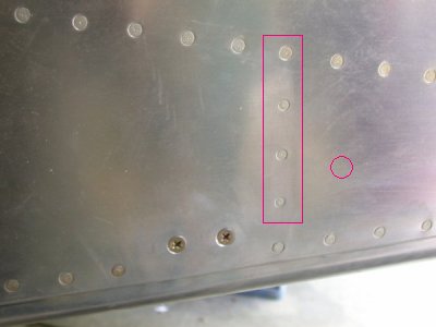
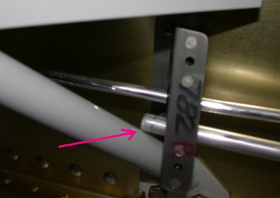
 Drilled holes in fwd side skin for fuel and vent lines. The RT edge of
the pic shows the 4 rivets I had to drill out. The top one is -4 and
the bottom 3 are -3.
Drilled holes in fwd side skin for fuel and vent lines. The RT edge of
the pic shows the 4 rivets I had to drill out. The top one is -4 and
the bottom 3 are -3.
June 10 - Did some shooting in the morning. Put screens on fuel vents and install them. Put AN fitting onto fuel selector valve. Install rudder cable snap bushings. Work on installing RT fuel vent line. 4.5 hr
![]() Primed 4 spacers to use with AN fittings for where fuel vent line goes out
to the wing.
Primed 4 spacers to use with AN fittings for where fuel vent line goes out
to the wing.
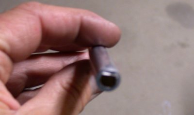
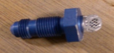 This shows
the screen I put over the end of the fuel vents. Sometimes digital
photography sucks - it's hard to tell in the monitor if it's in focus or not,
and if you try to get too close, it never focuses right, even with it set to
"macro" focus. The screen is held on with a bead of JB Weld
above and below the screen..
This shows
the screen I put over the end of the fuel vents. Sometimes digital
photography sucks - it's hard to tell in the monitor if it's in focus or not,
and if you try to get too close, it never focuses right, even with it set to
"macro" focus. The screen is held on with a bead of JB Weld
above and below the screen..
 Put teflon paste on the fuel control valve AN fittings and installed & tightened them.
 This
is the RT fuel vent line partially installed.
This
is the RT fuel vent line partially installed.
June 11 - Talked to Gus at Van's about how inverted fuel system is supposed to be laid out. Basically, QB builders are screwed, because it's so difficult to retrofit wing tanks once they're done. He says unless I plan extended inverted flight, it is not worth the trouble of setting up, plus I'd then need the trouble and expense of an inverted oil system, too. Finished RT fuel vent line. Installed LT fuel vent line. Had problems with one end of one piece of tubing kept splitting when I tried to flare it. Suspect a defect. Wrote Van's about it. Finally got it to flare on 4th (and last chance before that last piece got too short to use) attempt. Started on fuel lines, but decided to quit early, because I see a couple problems with it that I need to ask Van's about in the morning. 5.0 hr
 Another
poor pic that wouldn't focus. I never had any problems with flaring
before, but it took 4 attempts to get this end of this piece to flare
without splitting. After splitting this end three times, I tried the other
end, and it flared just fine. I did finally get it on the 4th
attempt, but I'll see what Van's has to say about it tomorrow. They
later said they'd had a problem in the past, but thought it was
resolved. They offered to send me more tubing, but I said I already
got it done OK.
Another
poor pic that wouldn't focus. I never had any problems with flaring
before, but it took 4 attempts to get this end of this piece to flare
without splitting. After splitting this end three times, I tried the other
end, and it flared just fine. I did finally get it on the 4th
attempt, but I'll see what Van's has to say about it tomorrow. They
later said they'd had a problem in the past, but thought it was
resolved. They offered to send me more tubing, but I said I already
got it done OK.
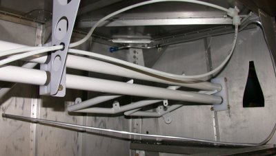
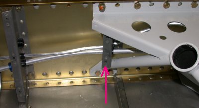
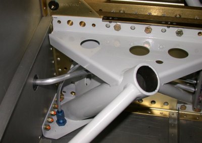
 Here's the left fuel vent system installed. It's the 1/4" line
that starts in the lower LT, goes up and over and finishes at the actual
vent opening in the floor, at lower RT. It went pretty smoothly.
That 1/4" aluminum tubing is pretty easy to work with. The orange
Adel clamp is an additional one I installed from my own stock. I
thought the vent lines were running too far unsupported right there, so I
added my own.
Here's the left fuel vent system installed. It's the 1/4" line
that starts in the lower LT, goes up and over and finishes at the actual
vent opening in the floor, at lower RT. It went pretty smoothly.
That 1/4" aluminum tubing is pretty easy to work with. The orange
Adel clamp is an additional one I installed from my own stock. I
thought the vent lines were running too far unsupported right there, so I
added my own.
June 12 - Went canoeing on a remote pond today. That was fun. Talked to Van's twice about problems trying to lay out the fuel lines. I found, and Van's confirmed, that it is a real BITCH to get the fuel lines in around the tri-gear WD-721 weldment. It's hard enough on a taildragger. The main problem is that you have to make an "S" turn between the weldment and the grommet hole, and then you have to "walk" the "S" down the stiff 3/8" tubing. I did finally get both LT and RT fuel lines installed, without having to divert from the layout as per the plans. Also installed RT rudder cable, just for the hell of it. I learned several important things about putting in 7A fuel lines.
If you are building a 7A, I STRONGLY recommend the following:
Put the fuel lines in BEFORE the brake lines
Put the fuel lines in BEFORE bolting the WD-721 gear mount weldment (put the weldment in place, but leave it loose, with no bolts, so it can move around for you).
When installing fuel lines, remove the screws holding the F-782B in place (when fastened down, causes significant interference between fuel line and WD-721 weldment inboard brace leg).
Don't put the rubber fuel line fuselage skin grommet in the 1" hole until after the fuel line is in place.
Run the fuel line through the middle hole in the weldment. The brake line will have to go through the top hole. The brake lines are much easier to deal with. My brake lines were running through the middle hole, so I had to pull them back out and reroute them. It wasn't pretty.
I was SOL on numbers 1 and 2 above, but doing numbers 3, 4, and 5 were what finally enabled me to get the brake lines in without going to Plan B, which was to forget trying to go through the weldment, as per the plans, and just run the fuel lines forward of the weldments (as low and aft as possible, so they're more protected). Gus at Van's (VERY helpful guy) said I could do that if I couldn't get the fuel lines in any other way. 5.5 hr
 My dooryard
has been inundated with these forest tent caterpillars lately. They
keep coming into the garage. I was tossing them back out, but then my
Mom said they are bad for trees and vegetation, so I started stepping on
them. Goosh!
My dooryard
has been inundated with these forest tent caterpillars lately. They
keep coming into the garage. I was tossing them back out, but then my
Mom said they are bad for trees and vegetation, so I started stepping on
them. Goosh!
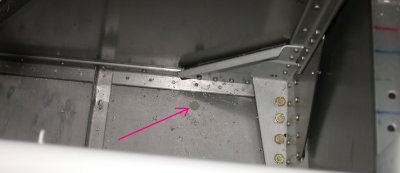
 Besides the big problem with the "S" bend, the other problem is
that the fuel line hits the weldment inboard brace leg. On the RT one,
I just bulled it past the leg. On the LT one, it was a little tighter,
and it was creasing the tubing. So, I learned to remove the screws
holding the 782 on, and that made it much easier.
Besides the big problem with the "S" bend, the other problem is
that the fuel line hits the weldment inboard brace leg. On the RT one,
I just bulled it past the leg. On the LT one, it was a little tighter,
and it was creasing the tubing. So, I learned to remove the screws
holding the 782 on, and that made it much easier.
 Another
poorly focused picture showing how the LT side weldment and 782 hole
interference caused creasing in the line as I pulled it through. Also,
being so tight made it very difficult to pull the tubing through.
Another
poorly focused picture showing how the LT side weldment and 782 hole
interference caused creasing in the line as I pulled it through. Also,
being so tight made it very difficult to pull the tubing through.
 This is
how I did it on the LT side; take the screws out of the 782 bracket, and
then it's no longer forcing the tubing to rub on the weldment leg as you
pull the tubing through.
This is
how I did it on the LT side; take the screws out of the 782 bracket, and
then it's no longer forcing the tubing to rub on the weldment leg as you
pull the tubing through.
![]() Once you finish running the line through the maze, then you go through it
all and make bends with your fingers to make sure the lines don't touch
anything but the grommets and snap bushings. You can see here where
the fuel line is now bent away from the weldment leg after everything is in its
place.
Once you finish running the line through the maze, then you go through it
all and make bends with your fingers to make sure the lines don't touch
anything but the grommets and snap bushings. You can see here where
the fuel line is now bent away from the weldment leg after everything is in its
place.
 The
way I finally got the lines through was to abandon the thought of making a
full "S" turn in the tubing. I removed the rubber grommet
from the hole and ran the tubing direct from the weldment, diagonally
through this hole. Once the line was in place, then I formed the
"S" on the other side of this skin, and put the grommet back
on. Don't scrape the tubing on the weldment or skin as you pull it
through this way. Keep bending it with your fingers as the tubing
comes through, to keep it away from the sides of the holes. Bend the
tubing against your fingers, not against the side of the hole or anything
else; that will crimp the tubing.
The
way I finally got the lines through was to abandon the thought of making a
full "S" turn in the tubing. I removed the rubber grommet
from the hole and ran the tubing direct from the weldment, diagonally
through this hole. Once the line was in place, then I formed the
"S" on the other side of this skin, and put the grommet back
on. Don't scrape the tubing on the weldment or skin as you pull it
through this way. Keep bending it with your fingers as the tubing
comes through, to keep it away from the sides of the holes. Bend the
tubing against your fingers, not against the side of the hole or anything
else; that will crimp the tubing.
 RT fuel
line installed. This shows the "S" turn the tubing has to
make once it is completely pulled through all the nooks and crannies.
The brake line is then wriggled around that. Make sure none of the
lines touch anything but their grommets. I recommend a minimum
1/8" gap. Once you get the tubing in place and the AN fittings
tightened, you can use your fingers to make fine adjustments in the routing.
RT fuel
line installed. This shows the "S" turn the tubing has to
make once it is completely pulled through all the nooks and crannies.
The brake line is then wriggled around that. Make sure none of the
lines touch anything but their grommets. I recommend a minimum
1/8" gap. Once you get the tubing in place and the AN fittings
tightened, you can use your fingers to make fine adjustments in the routing.
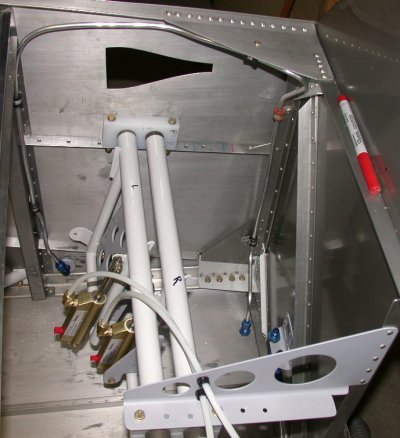
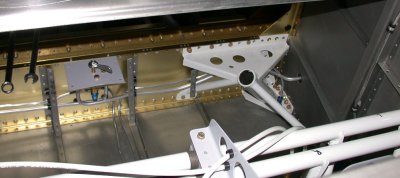 Both
fuel lines installed. As soon as my Van's order for fuel pump and
gascolator arrives, I will do the easy run from the center of the valve fwd
to the pump.
Both
fuel lines installed. As soon as my Van's order for fuel pump and
gascolator arrives, I will do the easy run from the center of the valve fwd
to the pump.
 I
decided to run one of the rudder cables through all the routing holes I had
already put snap bushings into. However, I soon found out that both
ends of the cable are too big to fit through the snap bushings. I
asked Van's about it, and they said just split the bushings. Then you
can put them over the cable, then push them into their holes. The
bushings cut easily.
I
decided to run one of the rudder cables through all the routing holes I had
already put snap bushings into. However, I soon found out that both
ends of the cable are too big to fit through the snap bushings. I
asked Van's about it, and they said just split the bushings. Then you
can put them over the cable, then push them into their holes. The
bushings cut easily.
BTW, one of the questions I asked Van's about was how far the fuel line is supposed to stick out from the fuselage. Ken wasn't real helpful about that, as he said "far enough to connect with the fuel tank fitting". He did explain that the wing skin is about 3" from the fuselage skin, before installing the root fairing. I had thought it would be flush, so I didn't understand how I'd have the wing out a couple inches to make the fuel connection, then push it in the rest of the way. Ken said it doesn't work that way; even with the wing all the way into the fuselage, there's plenty of room, especially on the top, to hook up the fuel lines. Anyway, I did my own calculation, and came up with 3.25" from the fuselage skin to the end of the tubing, before flaring. We'll see later if that is accurate. I sure hope it's not far off!
June 13 - worked on fuselage center uprights and sub panel assy. I kind of ran out of things to do, so I looked in the box of parts remaining, and these are what I found. Except for the roll bar assy, the box is nearly empty now. 4.0 hr
 This is
the LT upright clecoed into place. It didn't fit in there very
well. I'll have to be careful when I install it to not scrape all the
paint off the edges, where it scrapes by the adjoining pieces. Since
this piece is pop-riveted into place (I am assuming that - I cannot find ANY
info on fasteners for these pieces) and covers the main spar area, I will
wait until late in the game (after wings go in) to rivet these in. I
don't want to restrict any access to the space between the 2 spars.
This is
the LT upright clecoed into place. It didn't fit in there very
well. I'll have to be careful when I install it to not scrape all the
paint off the edges, where it scrapes by the adjoining pieces. Since
this piece is pop-riveted into place (I am assuming that - I cannot find ANY
info on fasteners for these pieces) and covers the main spar area, I will
wait until late in the game (after wings go in) to rivet these in. I
don't want to restrict any access to the space between the 2 spars.
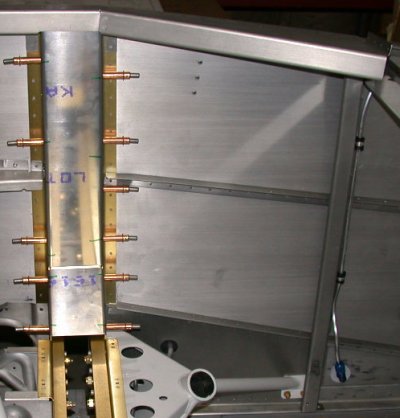
 Uprights all
primed and ready to set aside for later assembly.
Uprights all
primed and ready to set aside for later assembly.
 Karla stopped
by and helped some and kept me company by chatting with me.
Karla stopped
by and helped some and kept me company by chatting with me.
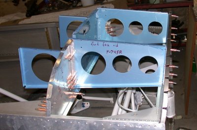 Here is
the sub panel assembly, partially clecoed together. There are even
more parts to put onto this assembly before it goes together. To get
this in, I had to remove what I am currently assuming is a temporary
shipping brace made of channel aluminum. I'll confirm this with
Van's. This is where I left off. Van's did confirm that the
aluminum U-channel that goes across the top of the fuselage here is just a
temporary shipping brace.
Here is
the sub panel assembly, partially clecoed together. There are even
more parts to put onto this assembly before it goes together. To get
this in, I had to remove what I am currently assuming is a temporary
shipping brace made of channel aluminum. I'll confirm this with
Van's. This is where I left off. Van's did confirm that the
aluminum U-channel that goes across the top of the fuselage here is just a
temporary shipping brace.
June 14 - Study inboard and outboard sub panel layout more. Trim F-643. Add F-643 and F-644 to sub panel layout. 1.0 hr
June 15 - Worked all day at LEB on Young Eagles event (ground support - no flying).
June 16 - Finally got my fuel pump from Van's today. Didn't have time to do anything with it, though, as I was busy getting ready to go do a contract in Manhattan for a few weeks. Got initial call in AM, offered job in PM, have to be onsite first thing tomorrow morning. More later!
June 27 - Get out FI fuel pump kit and gascolator. Look over parts and plans to see what to do next. The FI pump kit is MUCH more involved than the fuel pump for the carbureted engine. 1.5 hr
June 28 - More fuel pump layout. See also notes from April regarding this. Modify finished F-782C center cabin cover to accommodate FI fuel pump. Assemble F-7115 fuel pump cover. Set sub panel aside for now, to get the fuel pump and related parts installed before the sub panel is in the way. Modify finished F-983C fuel valve cover to accommodate FI fuel pump. Cleco & drill F-7115 fuel pump cover assy. Cleco nutplates onto various pieces making up the 7115 assy. Found that some of the nutplates for this need to be #6 and some are #8. 4.25 hr
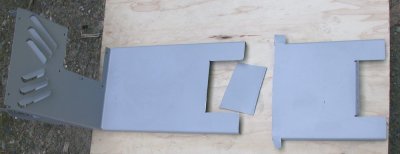 The pieces on the
RT are what had to be cut out of what I had thought was my finished F-782C
Center Cabin Cover.
The pieces on the
RT are what had to be cut out of what I had thought was my finished F-782C
Center Cabin Cover.
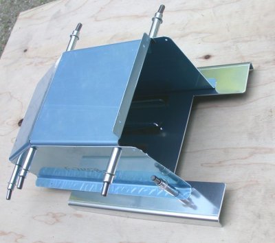 This is the F-7115 Fuel Pump Cover Assembly clecoed together. When
this is all put together, the fuel pump and fuel filter will be fastened to
the shiny piece on the bottom.
This is the F-7115 Fuel Pump Cover Assembly clecoed together. When
this is all put together, the fuel pump and fuel filter will be fastened to
the shiny piece on the bottom.
 Here's the clecoed fuel pump cover and the modified center cabin cover.
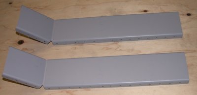
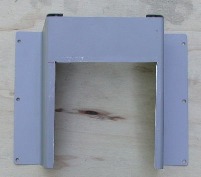
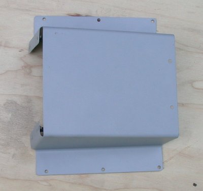 This is the
F-783C Fuel Valve Cover before modification.
This is the
F-783C Fuel Valve Cover before modification.
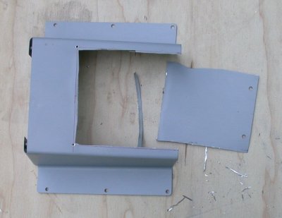 Here it is
after hacking a big chunk out of it.
Here it is
after hacking a big chunk out of it.
 And here it
is in final form.
And here it
is in final form.
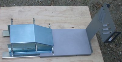
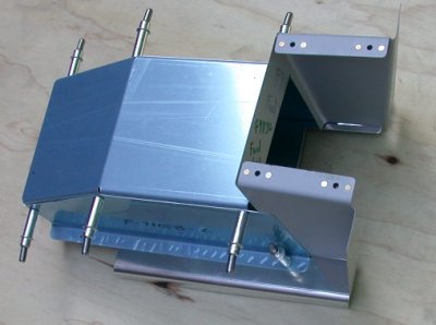 This
shows the F7115 Fuel Pump Cover and the modified F-783C Fuel Valve Cover
together.
This
shows the F7115 Fuel Pump Cover and the modified F-783C Fuel Valve Cover
together.
June 29 - Prep 7115 pieces for primer. Prime 7115 pieces, and rivet nutplates on. 3.75 hr
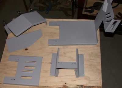 All
the pieces primed and all the nutplates riveted on. Only thing lacking
is riveting together the three pieces in the upper LT corner - the pump
cover. Due to the shapes, that will require a rivet gun and bucking
bar; no squeezing.
All
the pieces primed and all the nutplates riveted on. Only thing lacking
is riveting together the three pieces in the upper LT corner - the pump
cover. Due to the shapes, that will require a rivet gun and bucking
bar; no squeezing.
Back to NYC for the week!
June 30, 2003 - I just read an ad in the latest Sport Aviation that Eggenfellner is now offering a 200 HP Subaru. Uh-oh! I'll have to call and see if it's compatible with the FI pump I am now installing and the RV-7A cowl I have coming next week. Maybe I am still not decided; a 200 HP Subaru that will use my existing fuel pump and fit under my existing cowl would be great. See ENGINE page for details.
Go to JULY fuselage
BACK TO MY RV BUILDER'S HOME
BACK TO BRIAN'S HOME