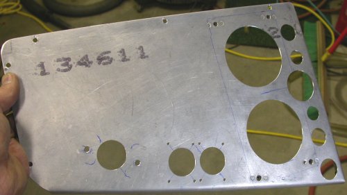
 Here is the removable electric components tray, with some lightening holes
drilled. Part of it remains undrilled, because I do not yet know what
will be mounted in the as-yet-unused space.
Here is the removable electric components tray, with some lightening holes
drilled. Part of it remains undrilled, because I do not yet know what
will be mounted in the as-yet-unused space.November, 2006 AVIONICS, ELECTRICS, & CONTROLS
A lot of what I am doing right now is wiring related toward getting the engine ready to start. If it's general supporting wiring, it's on this page. If it's strictly engine wiring, it's on the engine page, so be sure to check there for details. I'm also getting the console set up to support starting the engine.
Nov 1 - Wiring planning. More EIS wiring. Realized I'd made no provision for heater switch, nor do I know what to use for a switch for that (OFF-ON-ON-ON). Will query Eggenfellner list about it. Update web site 1.5 hr + 0.75 hr doc
Nov 2 - emailed Eggenfellner list about heater switch. They say it should have come with the heater kit. Add more wires to EIS harness. Remove inapplicable wires from supplied EIS harness. Replace supplied cheap DB sockets with machined sockets. Label remaining EIS wires. 0.5 hr
Nov 3 - Did more EIS wiring and getting the EIS DB-25 and MAP DB-9 connectors set up. Received reworked Perihelion Power Schottky modules. Looking at AoA mount possibilities. Looking around for heater switch. 2.0 hr
Nov 4 - emailed Jan about "no heater switch". Looking at OAT probes. The Dynon one is HUGE. Dynon has an integral harness not easily modified. It's 9'9" long, so that will limit where I can put the Dynon OAT probe, but it should be fine. Lay out Perihelion Power Schottky modules. Decided to slightly relocate primary battery contactor for better access to the main terminals. Found I will need to order more ring terminals to wire up the Power Schottky modules. Inventory my stock of ring terminals. 3.0 hr
Nov 6 - Started getting a cold yesterday, so feeling very miserable & not working on plane. Jan emailed me and said to get the missing heater switch direct from Heater Craft, so I called them. They will send me the switch and cover plate.
Nov 7 - realized by end of day that I was so ill I'd forgotten to order my terminals. Neither B&C nor SteinAir carried everything I needed, so I had to place orders with both, late in the day, so 2 days lost there in getting the terminals I need.
Nov 8 - Received heater switch, but no cover plate, from Heater Craft. Still sick.
Nov 10 - Happy USMC Birthday! Cold is starting to feel somewhat better. Talked to Steve at Heater Craft again. He will mail me the cover plate right away. Good customer service. Completed the homebuilt kitplanes directory I've been working on, and notified the few lists I am on about it. Emailed SteinAir about all the terminal sizes they didn't carry. Got reply that they stock them, but they hadn't updated their web site about it yet. Update web site. 2.0 hr doc
Nov 11 - looking at control stick grips and wiring for them. Will ask RV list about how people handle securing the wires. Removed components from removable electric tray and drilled lightening holes and reassembled. 2.0 hr
Here is the removable electric components tray, with some lightening holes
drilled. Part of it remains undrilled, because I do not yet know what
will be mounted in the as-yet-unused space.
Nov 12 - more pondering grips switches wire routing. Install engine ground strap and torque intake manifold bolt to 18 ft lb. Secure and protect ground strap. Clean up bench. 1.5 hr
Nov 13 - Asked Matronics RV list and Van's AF list about how people do the grip switch wiring routing, and got several good replies. Received and put away B&C order. 0.25 hr
Nov 14 - Received MT prop controller. Received and put away SteinAir order. Install terminals to connect contactors and Power Schottky diodes. Did it several times until I was satisfied with it. Lay out and plan routing for wire bundle to get wires to fuse blocks and switches panel. 4.0 hr
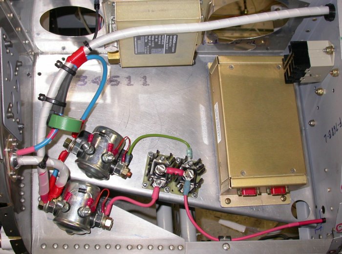 This pic shows the Power Schottky diodes wired and the rest of the
electric components installed so far. The main leads from the batteries will
come in between the removable tray and the LT edge of fuselage. This
pic shows #6 starter wire, alternator B lead, main and engine contactors,
contactors interconnect, GRT HE current sensor and its output lead going
inboard, #6 wire going aft to feed main fuse blocks, Power Schottky diodes
and leads to contactors, as well as lead going aft to engine bus. It
also shows the Sandia encoder, BMA A/P controller, and as-yet-unused Omron
relay. The nuts on the fwd side of the subpanel (far RT in pic) are
holding the main fuse blocks on the aft side of the subpanel.
This pic shows the Power Schottky diodes wired and the rest of the
electric components installed so far. The main leads from the batteries will
come in between the removable tray and the LT edge of fuselage. This
pic shows #6 starter wire, alternator B lead, main and engine contactors,
contactors interconnect, GRT HE current sensor and its output lead going
inboard, #6 wire going aft to feed main fuse blocks, Power Schottky diodes
and leads to contactors, as well as lead going aft to engine bus. It
also shows the Sandia encoder, BMA A/P controller, and as-yet-unused Omron
relay. The nuts on the fwd side of the subpanel (far RT in pic) are
holding the main fuse blocks on the aft side of the subpanel.
After I got the GRT Hall Effect current sensor all installed, lots of people on the GRT list are saying that the thing is wildly inaccurate. That sucks. Well, I'll just have to deal with it once I get all this stuff working.
Nov 15 - received Heatercraft switch plate for heater switch. Planning mounting switch panel to main instrument panel. It will be tricky to mount, because I want it to be removable and there is no room at all between the bottom of the BMA EFIS and the top of the bottom flange on the instrument panel. So, somehow I have to make a stud that is flush-mount to the top of the instrument panel flange and projects below the flange. 1.25 hr
Nov 16 - Ordered more nylon slit-convoluted tubing from McMaster-Carr for wiring protection. Also ordered some "press-in captive studs", which may resolve my dilemma about how to mount the switches panel. Update web site 1.0 hr doc
Nov 20 - fit switch panels to instrument panel. Route, label, apply terminals to switch panel wires. Day/night temperatures are now in the 30s/20s, so I've begun running the heater in the garage. 3.25 hr
Nov 21 - received McMaster-Carr and MSC orders. I was eager to try out the press-in captive studs from McMaster. It all went extremely well; very simple & effective. Spent the rest of the evening continuing to wire up the engine/battery switch panel. 3.0 hr
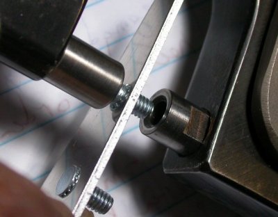 This is a closeup of some captive studs I practiced installing in a scrap of
0.063" aluminum. It was very simple to do. I had planned to make
a die for my rivet squeezer to press in the studs. Then I realized
that the #8 studs are smaller in diameter than the 3/16" holes in the
squeezer for the rivet sets, so I simply used the existing hole in the
plunger. I drilled the metal to #20 and just squeezed in the studs.
They seem very tight. I'd planned to also use red Loctite, but I don't
think it will be necessary. The lower stud in the pic is pressed in
tight, but I later pressed it in more, so the head is completely flush.
Doing that made the aluminum plate curve a bit, but when I did it on the leg
of a (stiffer) piece of 0.062" angle, it stayed straight while getting the
head flush. I also ended up reversing the roles shown: I put the stud
into the hole in the C-frame and put a larger diameter rivet set into the
hole in the plunger. It seemed to distort the metal less that way, due
to larger surfaces pressing against the plate.
This is a closeup of some captive studs I practiced installing in a scrap of
0.063" aluminum. It was very simple to do. I had planned to make
a die for my rivet squeezer to press in the studs. Then I realized
that the #8 studs are smaller in diameter than the 3/16" holes in the
squeezer for the rivet sets, so I simply used the existing hole in the
plunger. I drilled the metal to #20 and just squeezed in the studs.
They seem very tight. I'd planned to also use red Loctite, but I don't
think it will be necessary. The lower stud in the pic is pressed in
tight, but I later pressed it in more, so the head is completely flush.
Doing that made the aluminum plate curve a bit, but when I did it on the leg
of a (stiffer) piece of 0.062" angle, it stayed straight while getting the
head flush. I also ended up reversing the roles shown: I put the stud
into the hole in the C-frame and put a larger diameter rivet set into the
hole in the plunger. It seemed to distort the metal less that way, due
to larger surfaces pressing against the plate.
 Putting labels and terminals onto the wires to the engine/battery switch
panel. Also adding a wire from each switch back to the appropriate
fuse block. I'm making each wire about a foot longer than minimum, so
I can pull the panel out without having to disconnect all those switch
terminals. Also, as mentioned above, the switch panels will be
removable from the main panel, through the use of the press-in captive
studs.
Putting labels and terminals onto the wires to the engine/battery switch
panel. Also adding a wire from each switch back to the appropriate
fuse block. I'm making each wire about a foot longer than minimum, so
I can pull the panel out without having to disconnect all those switch
terminals. Also, as mentioned above, the switch panels will be
removable from the main panel, through the use of the press-in captive
studs.
Nov 22 - update web site 1.0 hr doc
Nov 23 - Happy Thanksgiving to all!!!
Nov 26 - resume switch panel wiring. Add wires to fuse blocks. Route & secure wires 5.0 hr
Nov 27 - more switch panel wiring - route, label, apply terminals to switch panel wires going to fuse blocks 1.5 hr
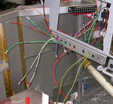
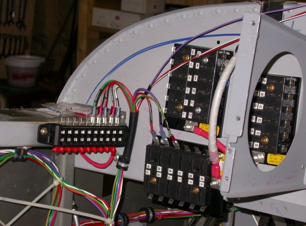 Here is my start to wiring the switches to the fuse blocks. I am
keeping notes on each wire installed (size, color, use, destination,
etc) for my wiring documentation.
Here is my start to wiring the switches to the fuse blocks. I am
keeping notes on each wire installed (size, color, use, destination,
etc) for my wiring documentation.
go to December, 2006 wiring
BACK TO MY RV BUILDER'S HOME
BACK TO BRIAN'S HOME