A lot of what I am doing right now is wiring related toward
getting the engine ready to start. If it's strictly engine wiring, it
on this page. If it's more general supporting wiring, it's on the
avionics/electric page, so be sure to check there for details
Sep 1 - Finalizing fit of
wastegate actuation parts to SC tubing. Decided to order some 1" x 1"
x 1/16" aluminum angle from Wicks, instead of the 1" x 1" x 1/8"
and 3/4" x 3/4" x 1/16" angle I
currently have. I will get this welded to the SC tubing so I can mount
the Bowden cable clamp. Took tubing and AN912-4D reducer to welding
shop to get the reducer welded to the tubing. Ordered the aluminum angle and a 2-lever
throttle quadrant from Wicks. Drill out firewall for the 2-wire
eyeball clamp for the starter and alternator battery wires.
2.5 hr
Sep 3 - Install firewall eyeball
fitting and install, secure, protect the alternator battery wire and starter
wire. Install starter wire to primary contactor.
2.5 hr
This is the aft view of the Schultz firewall eyeball fitting, with the
starter and alt-B wires coming through it. The starter wire has the
thick, heavy nylon spiral wrap on it as it comes through the fitting, and
the alt-B wire has a layer of heatshrink on it as it passes through the
fitting.
This is the fwd view of the eyeball fitting, with 2 layers of corrugated
tubing protecting the 2 wires.
Sep 5 - update web site
1.5 hr doc
Sep 6 - picked up welded SC
tubing. Drill out AN912-4D and tubing to 9/16". Lay out and
plan for angle to support Bowden cable clamp. Still waiting
for Wicks order of aluminum 1" angle and 2-lever throttle quadrant.
0.5 hr
Sep 7 - received Wicks order.
Cut 1" angle aluminum with 2 1/8" cutter and fit it to the SC tubing.
1.5 hr
Using the mill, a holesaw, and the Avery round tubing clamp extrusion to cut
the 1" angle at a 45 degree angle and a 2 1/8" radius. I could have
clamped the angle down flat and turned the mill head 45 degrees, but this
was easier.
This is the mount for the Bowden cable clamp, cut, fitted, and all ready to
weld.
Sep 8 - update web site
0.5 hr doc
Sep 9 - Looking at the quadrant I
received from Wicks. Realized it isn't going to work. The
max travel I can get from it is about 1 3/4", and the Gary Newsted
Electronic Throttle Assembly needs 2". Will have to send it back.
Found out Wicks charges 15% restocking for all returns; not happy to hear
that.
0.5 hr
Sep 11 - Remember the 9/11
attacks! Ordered new, larger
2-lever throttle quadrant from ACS. It is backordered, with a 3-4 week
lead time. Took the aluminum to the welding shop and got the Bowden
cable clamp mount welded on. Installed wastegate components onto SC
tubing. Even though I'd taken great pains in marking the bracket
location and in making sure it was on the marks before welding, I had to do
some tweaking of the angle bracket to achieve an ideal fit of the cable
alignment to the ball valve. Update web site.
1.25 hr + 0.5 hr doc
Here is the Bowden cable clamp mount bracket welded on. This end of
the whole wastegate control mechanism is ready to put together. Now, I
just have to wait another month to get the throttle quadrant for the other
end. I sure hope it will work this time.
Sep 15 - finalize fit of
wastegate control. It will need about 1.75" travel. Safety ball
valve lever nut, cut lever down to final size, safety Bowden cable end
fitting. Shorten battery cable to primary contactor.
1.5 hr
Here is the completed wastegate end of the wastegate control system.
The Bowden cable clamp is at 45 degrees to the ball valve, to give it
maximum control and minimum friction.
Sep 21 - I noted that the
hardware securing the RT side engine wiring harness firewall passthru had a
layer of apparent corrosion on it. While I have never experienced
anything like this before from using RTV, I can only assume it came from the
acetic acid fumes released as the RTV cured. Removed and replaced all
hardware securing the RT firewall harness passthru. Laid out a better
hole location for the LT engine harness firewall passthru. On the LT
side, I fabricated a custom s/s passthru. After dealing with the
Schultz Engineering metal firewall eyeball grommets (available from ACS), I
realized I could have done in easier with a Schultz eyeball, so that's what
I'll be using for the LT passthru. I already used one of the Schultz
eyeballs to do the starter and alternator battery wires through the
firewall. 1.0 hr
This is some of the hardware for attaching the LT engine wiring harness
firewall passthru. Old hardware on RT, new hardware on LT. Very
odd that these got corroded like this shortly after they were installed.
The only explanation I can think of is that acetic acid fumes from RTV
curing caused it, as I used hi-temp RTV silicone sealant to seal the passthru. I've
used RTV thousands of times for sealing all sorts of stuff, but I've never seen it
do anything like this. I replaced all the hardware.
Sep 24 - Drill holes in
firewall for Schultz eyeball grommet, fine-tune misaligned grommet mount
screw holes (holes seem to love to "walk" when drilling s/s). Feed
LT engine wiring harness thru eyeball grommet hardware. Cut and
splice wires for LT harness to get the connectors through the hole, and
to remove excess length. 5.0 hr
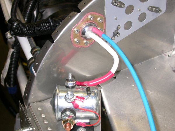
Here is the Schultz metal firewall eyeball grommet (without the split
eyeball for now), with the wires for the first couple LT engine connectors
going through it. When I am sure I have accounted for all possible
wires to go through here, I will drill the split metal eyeball for the
appropriate size hole and install it. These Schultz eyeball grommets
(available thru Aircraft Spruce) are great. If I later add more wires,
it's easy to remove the split metal ball and drill the center hole a bit
bigger. Bottom of pic shows Andair firewall fuel filter and fuel
pressure sensor and switch, with 3/8" aluminum tubing going up to the fuel
rail.
Sep 25 - Stopped by local Subaru
dealer to try to find tool for removing terminals from the Subaru engine
wiring harness connectors. They weren't very interested in being
helpful, and they didn't seem to have any specific tools or knowledge, but
they did at least give me some insight into how the connectors go together.
It's hard to describe, but the orange cap has to be removed separately
before the terminals can be removed. The orange caps form a double
lock on the terminals; they lock the terminal locks into place. It
remains a bit of a mystery as to exactly how the orange caps are supposed to
come off, other than general prying, digging, and mangling. Net effect
is that it's still easier to cut & splice the wires than to try to pull the
terminals. Too bad; if I had the "right" tool, I'm sure it would be as
simple as pulling terminals from a DB or Molex connector. Update web
site 1.0 hr + 2.0 hr doc
Sep 26 - ordered current limiter
(for alt-B, to replace current plan of using a panel-mounted 60a breaker,
resulting in most of the alt-B run being unprotected), engine ground strap,
and a few other goodies from B&C. Finished cutting and splicing wires
to the LT engine wiring harness connectors.
3.0 hr + 1.0 hr doc
Sep 27 - remade the oxy heater
power lead, as the one that came with the engine was too short to reach the
fuse blocks. Reinstalled ECM and secured all wiring to and around it.
Made wire run from fuse blocks area to ECM power distribution strip.
Agonized awhile over what wire size to use for that, as I'd never gotten any
straight answers from anyone on how much current the ECM will draw.
Gary's schematic just tacks it onto a 20 breaker circuit, without specifying
wire diameter to the ECM. Jan's original +12v wiring was mostly
(auto-type) 14ga. An earlier email from Jan in response to my queries
about this said to allow for a 10a fuse for the ECM. My wiring diagram
had said 18ga (probably based on Jan's email), but 18ga looked so puny
compared to the Subaru wires in my +12v distribution block, I wasn't
comfortable with it. Even 18ga should be plenty, as my wiring chart
says it will handle 10a for 11 feet. I also did a test by powering up
the ECM and measuring what it drew. It surged to 5a for a second, then
fluttered a bit around 2-3a, then dropped to about 1.5a. Of course,
this is with the engine not running, so a running engine will no doubt draw
more. In the end, I compromised and went with 16ga.
Organized and secured wires from ECM to LT side. The wiring is
starting to take shape a bit! 5.0 hr + 0.5 hr
doc
 This is the aft view of the Schultz firewall eyeball fitting, with the
starter and alt-B wires coming through it. The starter wire has the
thick, heavy nylon spiral wrap on it as it comes through the fitting, and
the alt-B wire has a layer of heatshrink on it as it passes through the
fitting.
This is the aft view of the Schultz firewall eyeball fitting, with the
starter and alt-B wires coming through it. The starter wire has the
thick, heavy nylon spiral wrap on it as it comes through the fitting, and
the alt-B wire has a layer of heatshrink on it as it passes through the
fitting.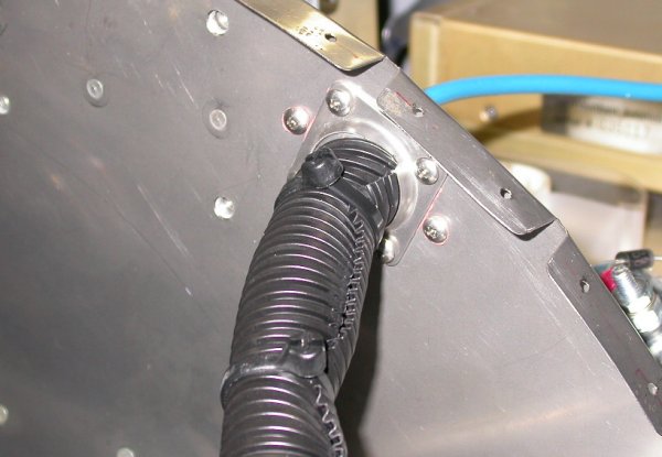 This is the fwd view of the eyeball fitting, with 2 layers of corrugated
tubing protecting the 2 wires.
This is the fwd view of the eyeball fitting, with 2 layers of corrugated
tubing protecting the 2 wires.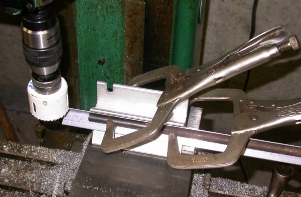 Using the mill, a holesaw, and the Avery round tubing clamp extrusion to cut
the 1" angle at a 45 degree angle and a 2 1/8" radius. I could have
clamped the angle down flat and turned the mill head 45 degrees, but this
was easier.
Using the mill, a holesaw, and the Avery round tubing clamp extrusion to cut
the 1" angle at a 45 degree angle and a 2 1/8" radius. I could have
clamped the angle down flat and turned the mill head 45 degrees, but this
was easier.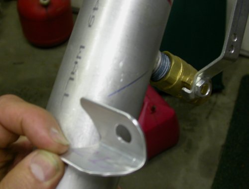 This is the mount for the Bowden cable clamp, cut, fitted, and all ready to
weld.
This is the mount for the Bowden cable clamp, cut, fitted, and all ready to
weld.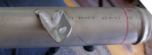 Here is the Bowden cable clamp mount bracket welded on. This end of
the whole wastegate control mechanism is ready to put together. Now, I
just have to wait another month to get the throttle quadrant for the other
end. I sure hope it will work this time.
Here is the Bowden cable clamp mount bracket welded on. This end of
the whole wastegate control mechanism is ready to put together. Now, I
just have to wait another month to get the throttle quadrant for the other
end. I sure hope it will work this time.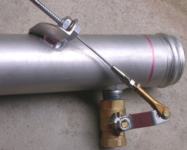 Here is the completed wastegate end of the wastegate control system.
The Bowden cable clamp is at 45 degrees to the ball valve, to give it
maximum control and minimum friction.
Here is the completed wastegate end of the wastegate control system.
The Bowden cable clamp is at 45 degrees to the ball valve, to give it
maximum control and minimum friction.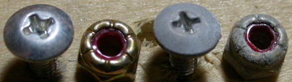 This is some of the hardware for attaching the LT engine wiring harness
firewall passthru. Old hardware on RT, new hardware on LT. Very
odd that these got corroded like this shortly after they were installed.
The only explanation I can think of is that acetic acid fumes from RTV
curing caused it, as I used hi-temp RTV silicone sealant to seal the passthru. I've
used RTV thousands of times for sealing all sorts of stuff, but I've never seen it
do anything like this. I replaced all the hardware.
This is some of the hardware for attaching the LT engine wiring harness
firewall passthru. Old hardware on RT, new hardware on LT. Very
odd that these got corroded like this shortly after they were installed.
The only explanation I can think of is that acetic acid fumes from RTV
curing caused it, as I used hi-temp RTV silicone sealant to seal the passthru. I've
used RTV thousands of times for sealing all sorts of stuff, but I've never seen it
do anything like this. I replaced all the hardware.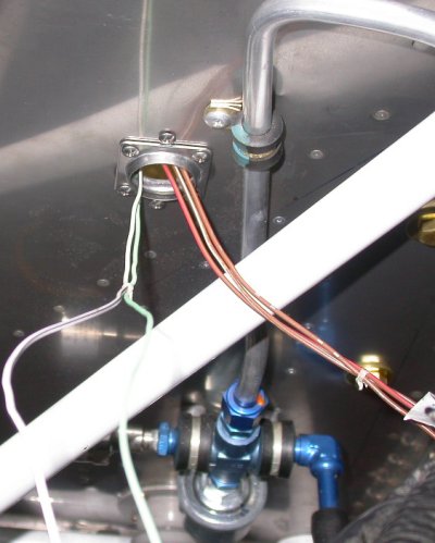 Here is the Schultz metal firewall eyeball grommet (without the split
eyeball for now), with the wires for the first couple LT engine connectors
going through it. When I am sure I have accounted for all possible
wires to go through here, I will drill the split metal eyeball for the
appropriate size hole and install it. These Schultz eyeball grommets
(available thru Aircraft Spruce) are great. If I later add more wires,
it's easy to remove the split metal ball and drill the center hole a bit
bigger. Bottom of pic shows Andair firewall fuel filter and fuel
pressure sensor and switch, with 3/8" aluminum tubing going up to the fuel
rail.
Here is the Schultz metal firewall eyeball grommet (without the split
eyeball for now), with the wires for the first couple LT engine connectors
going through it. When I am sure I have accounted for all possible
wires to go through here, I will drill the split metal eyeball for the
appropriate size hole and install it. These Schultz eyeball grommets
(available thru Aircraft Spruce) are great. If I later add more wires,
it's easy to remove the split metal ball and drill the center hole a bit
bigger. Bottom of pic shows Andair firewall fuel filter and fuel
pressure sensor and switch, with 3/8" aluminum tubing going up to the fuel
rail.