 Here is the Grand Rapids Hall Effect sensor. GRT says it can be
mounted about anywhere; on a wall the wire passes through, or even "just use
wire ties to hold it in place on a wire", as Sandy at GRT told me.
Here is the Grand Rapids Hall Effect sensor. GRT says it can be
mounted about anywhere; on a wall the wire passes through, or even "just use
wire ties to hold it in place on a wire", as Sandy at GRT told me.September, 2006 AVIONICS, ELECTRICS, & CONTROLS
A lot of what I am doing right now is wiring related toward getting the engine ready to start. If it's general supporting wiring, it's on this page. If it's strictly engine wiring, it's on the engine page, so be sure to check there for details
Sep 3 - install and label third main fuse block 0.5 hr
Sep 6 - ordered Grand Rapids Hall Effect current sensor. It was $60 vs $40 at Allied, but Allied and Cypress Test (FW Bell) are still saying 12 week lead time (they also said 12 weeks back in July), and I was sick of fooling around with them.
Sep 9 - received GRT Hall Effect sensor
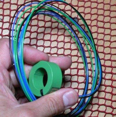
Here is the Grand Rapids Hall Effect sensor. GRT says it can be
mounted about anywhere; on a wall the wire passes through, or even "just use
wire ties to hold it in place on a wire", as Sandy at GRT told me.
Sep 15 - Ponder wiring, route alternator battery wire and main battery wire aft through subpanel. Wire main fuse blocks to primary contactor. After cutting engine bus fuse block wires to make it into 2 separate busses, I suddenly saw the light about what I guess Eric was trying to tell me about redoing my wiring diagram to make it simpler. Spent an hour or so making up new wiring block diagrams. 4.0 hr
 Current wiring block diagram. I already bought the expensive locking
4PDT switches for it. Maybe it's too complex? For the fuel
pumps, this gives me switches in series with switches, which is unnecessary
and just an additional component to buy, install, and to possibly fail. Click on it for a
larger image.
Current wiring block diagram. I already bought the expensive locking
4PDT switches for it. Maybe it's too complex? For the fuel
pumps, this gives me switches in series with switches, which is unnecessary
and just an additional component to buy, install, and to possibly fail. Click on it for a
larger image.
 This is the proposed simplified block diagram. It eliminates the 4PDT
switches (although I've already bought them and don't know if I can return
them) and having to buy so many Schottky diodes, but I wonder how the
Schottky diodes will handle it if one battery is at a lower voltage than the
other. Maybe it's better than the one above, maybe not. I will
ask the AeroElectric list about it. Click on it for a larger view.
SEP 21 UPDATE - people on the AeroElectric list tell me the bus will always
see the higher voltage, so it's OK there. OCT UPDATE - this
block diagram is what I decided to go with on my wiring. I returned
the two 4PDT switches to Allied OK.
This is the proposed simplified block diagram. It eliminates the 4PDT
switches (although I've already bought them and don't know if I can return
them) and having to buy so many Schottky diodes, but I wonder how the
Schottky diodes will handle it if one battery is at a lower voltage than the
other. Maybe it's better than the one above, maybe not. I will
ask the AeroElectric list about it. Click on it for a larger view.
SEP 21 UPDATE - people on the AeroElectric list tell me the bus will always
see the higher voltage, so it's OK there. OCT UPDATE - this
block diagram is what I decided to go with on my wiring. I returned
the two 4PDT switches to Allied OK.
Sep 19 - scan the 2 wiring block diagrams I made, and post questions on AeroElectric list. Fasten fuse blocks to subpanel. 1.25 hr
 Here are the 3 main fuse blocks installed on the subpanel. They will be
easily accessible when the canopy is up. They are tied together and to the
switched side of the primary contactor, shown at LT edge of pic.
Just above the primary contactor, you can see where the starter and alternator
battery wires go through the Schultz eyeball grommet in the firewall.
Maximize this window and click on pic for a larger
view.
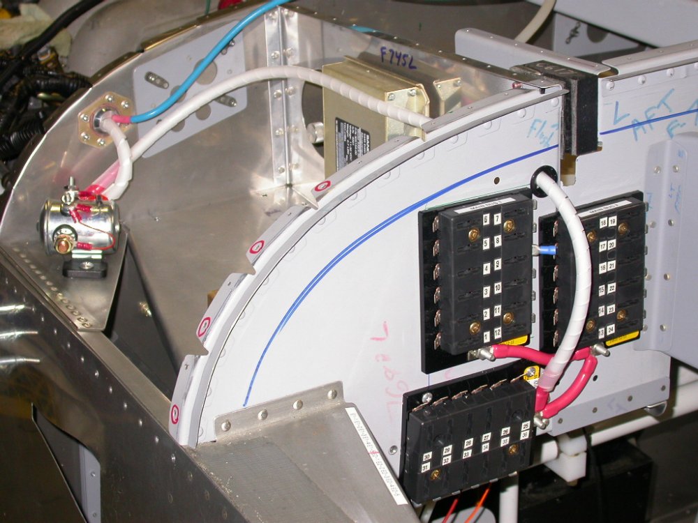
Here are the 3 main fuse blocks installed on the subpanel. They will be
easily accessible when the canopy is up. They are tied together and to the
switched side of the primary contactor, shown at LT edge of pic.
Just above the primary contactor, you can see where the starter and alternator
battery wires go through the Schultz eyeball grommet in the firewall.
Maximize this window and click on pic for a larger
view.
Sep 20 - install ground block and lay out hole for LT side wiring to go through firewall. 1.0 hr
 Here is the ground plate installed. I chose this spot as being
accessible, yet using space that would otherwise be wasted.
Click on it for a more detailed view. This is with the removable
panel (for the BMA A/P controller and other yet-to-be-determined
components) removed. I have to be careful as I add components here
that I keep that panel removable. That's why I had to shorten the
main battery cable between the contactor and the starter - so it didn't
interfere with the removable panel.
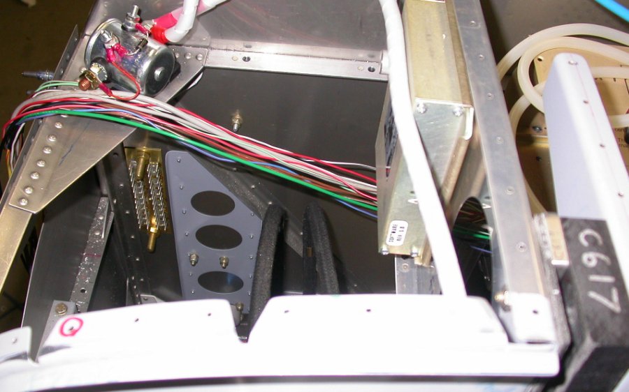
Here is the ground plate installed. I chose this spot as being
accessible, yet using space that would otherwise be wasted.
Click on it for a more detailed view. This is with the removable
panel (for the BMA A/P controller and other yet-to-be-determined
components) removed. I have to be careful as I add components here
that I keep that panel removable. That's why I had to shorten the
main battery cable between the contactor and the starter - so it didn't
interfere with the removable panel.
Sep 22 - call Allied about returning the 2 expensive ($75 ea) 4PDT locking switches. They will fax me a RMA. Still undecided on exactly what electrical block diagram layout I will go with, but I now think the 4PDT switches thing is not necessary. Most AeroElectric replies suggested going with something like the second diagram, but I just haven't decided on final details yet.
Sep 27 - email GRT about instructions and guidelines for mounting their Hall Effect current sensor.
Sep 29 - Still pondering how I should configure the engine bus. In the end, I decided to go back to one engine bus, fed by 2 batteries through Perihelion's Power Schottky diodes. Removed the E-bus jumpers I'd made from 14ga wire and Faston terminals. Drilled out Faston tabs to #30 and ran stripped 12ga wire through all tabs on one side. Soldered the wire to all tabs, then put on a coat of liquid insulation. 1.5 hr
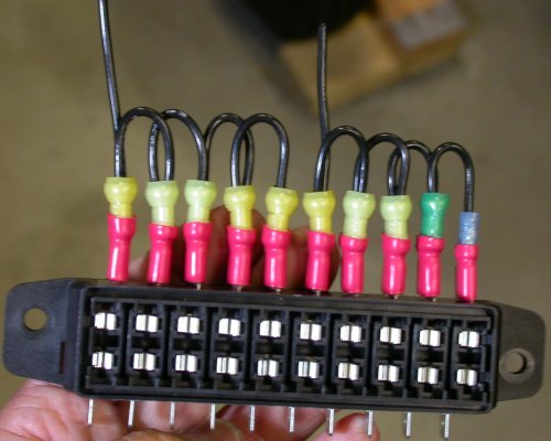 I had the E-bus wired up as one bus with all these jumpers, then I came up
with the plan that called for 2 E-busses, so I split it. As soon as I
got it split, then I decided to go back to one E-bus. So, I pulled all
these jumpers.
I had the E-bus wired up as one bus with all these jumpers, then I came up
with the plan that called for 2 E-busses, so I split it. As soon as I
got it split, then I decided to go back to one E-bus. So, I pulled all
these jumpers.
 To
re-jumper the feed tabs, I decided to just add one 12ga wire through all of
them, as opposed to all those time-consuming Faston connectors & little 14ga
jumpers I used on the last iteration. I drilled all the Faston tabs
out to #30, then stripped several inches of insulation from this 12ga wire,
and ran the wire through the holes.
To
re-jumper the feed tabs, I decided to just add one 12ga wire through all of
them, as opposed to all those time-consuming Faston connectors & little 14ga
jumpers I used on the last iteration. I drilled all the Faston tabs
out to #30, then stripped several inches of insulation from this 12ga wire,
and ran the wire through the holes.
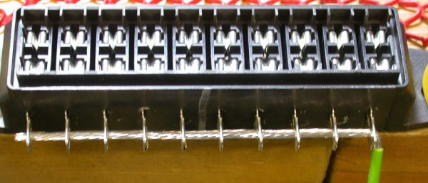
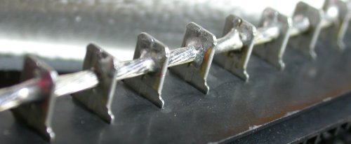 Here are all the Faston tabs, soldered to the 12ga wire.
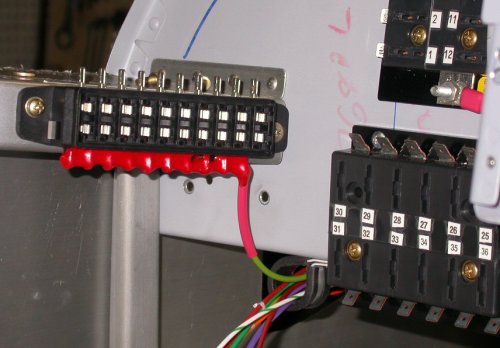 Here is the E-bus, ver 3, with the hot input side covered in liquid
insulation, plus a layer of tool handle dip, reinstalled in the plane.
Here is the E-bus, ver 3, with the hot input side covered in liquid
insulation, plus a layer of tool handle dip, reinstalled in the plane.
GO TO OCTOBER, 2006 AVIONICS/ELECTRIC
BACK TO MY RV BUILDER'S HOME
BACK TO BRIAN'S HOME