 Here, I am working on the EIS harness, bringing the Manifold Pressure Sensor
leads into it. The high quality machined pins and the 4-way crimper
work great! I found I need to trim 5/32" of insulation from the wire
ends for the pins.
Here, I am working on the EIS harness, bringing the Manifold Pressure Sensor
leads into it. The high quality machined pins and the 4-way crimper
work great! I found I need to trim 5/32" of insulation from the wire
ends for the pins.October, 2006 AVIONICS, ELECTRICS, & CONTROLS
A lot of what I am doing right now is wiring related toward getting the engine ready to start. If it's general supporting wiring, it's on this page. If it's strictly engine wiring, it's on the engine page, so be sure to check there for details
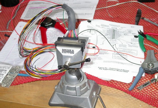
Oct 1 - Put a second coat of liquid insulation onto E-bus, using that rubbery dip stuff for coating tool handles. Clean up bench. Start looking at Grand Rapids EIS hookup. For some odd reason, GRT does not have the EIS installation manual online on their document downloads page, so HERE it is. Email me for a JPG of the EIS wiring diagram for Eggenfellner engines. Installed GRT Manifold Pressure Sensor box and wired it to the EIS. It will also need a vacuum line run to it. 8.0 hr
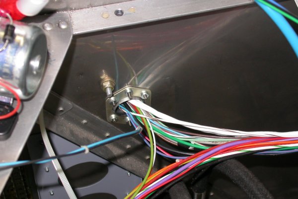
Here, I am working on the EIS harness, bringing the Manifold Pressure Sensor
leads into it. The high quality machined pins and the 4-way crimper
work great! I found I need to trim 5/32" of insulation from the wire
ends for the pins.
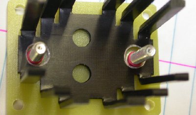
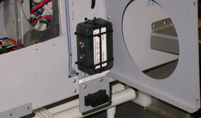 Here is the installed MAP sensor for the GRT EIS. Mounted below it on
the instrument subpanel is the OBD diagnostics port for the engine ECM.
Here is the installed MAP sensor for the GRT EIS. Mounted below it on
the instrument subpanel is the OBD diagnostics port for the engine ECM.
Oct 2 - still waiting for Allied to send me that RMA fax. Posted several questions to Eggenfellner list about EIS wiring. Update web site 2.0 hr doc
Oct 4 - run PSRU temp, coolant temp, tach, and fuel flow wires to EIS. Trim wires to length, print wire labels, crimp sockets onto the 4 wires. Secure wiring harness. Add wire labels to the 3 EIS wires (MAP sensor) I did a couple days ago. 2.5 hr
Oct 5 - Called Allied & asked "Where is my RMA?" They claim it will be faxed today. It's been over 2 weeks since I requested it. Got Allied RMA & packed up switches & relays to return. Update web site 1.0 hr doc
Oct 11 - Final DIRTY DEAL on the sleazy, crooked hangar situation at Claremont Municipal Airport. Re-route oil temp and oil pressure wires. Mount engine battery contactor to removable tray. 1.5 hr
Oct 12 - Ponder further on how to route the coolant level sensor wiring. One path is only about a foot, but it means making another hole and passthru for the firewall on the RT side. The other path takes it all around the perimeter of the engine, then through the existing firewall hole on the LT, then back along the aft side of the firewall to the RT side again and then to the EIS. Probably about 10' of wire vs 1'. 0.5 hr
Oct 13 - Realized coolant level sensor wires destination is on LT side of cockpit, not EIS on RT, so decided to route the wires around the engine. Worked to 0300 on that. 2.5 hr
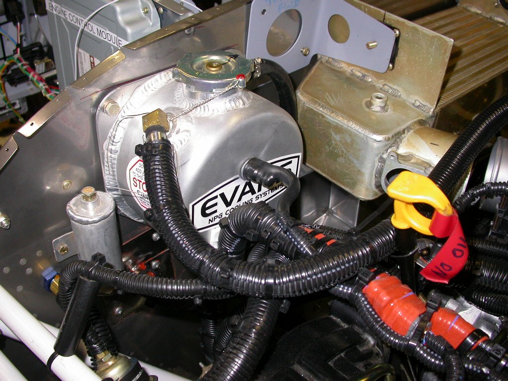 The coolant level sensor and wires are all installed, protected, and secured.
That's 2 layers of dual wall heatshrink on the sensor and the 2 wires
coming from the sensor in the middle of the coolant tank, followed by
corrugated tubing to the firewall passthru. Click on pic for larger overall pic of RT side of engine thus far.
The coolant level sensor and wires are all installed, protected, and secured.
That's 2 layers of dual wall heatshrink on the sensor and the 2 wires
coming from the sensor in the middle of the coolant tank, followed by
corrugated tubing to the firewall passthru. Click on pic for larger overall pic of RT side of engine thus far.
Oct 14 - reinstalled intercooler temporarily to route wiring around it. Secure coolant level wires. Remembered one more set of wires I have to do on engine - MT controller wires to hub, so I laid those in place for now. 2.0 hr
Oct 15 - The MT prop controller wiring connector on the controller end comes fully finished, and not easy to redo, so I will have to wait until I get my console and my MT controller back from MT upgrade to see exactly where the connector will go. Worked to 0245 laying out wires for fuel pressure transducer and low fuel pressure switch. 3.75 hr
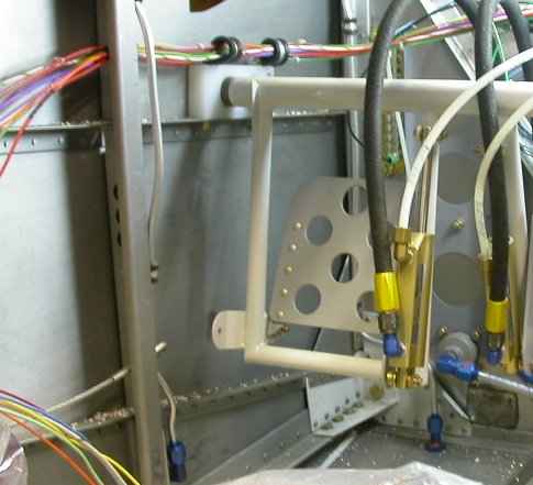
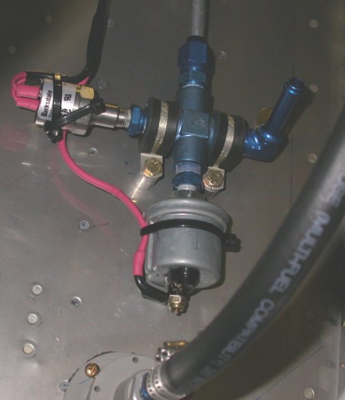 Here, the fuel pressure transducer and switch are wired, protected with
multiple layers of heatshrink tubing, and secured. There will also be
corrugated tubing protection on the upper part, once I finalize the wires
through the firewall passthru. The Andair fuel filter is on the bottom
of the pic, and the hose from it goes up to the AN hose fitting at the AN
fuel tee.
Here, the fuel pressure transducer and switch are wired, protected with
multiple layers of heatshrink tubing, and secured. There will also be
corrugated tubing protection on the upper part, once I finalize the wires
through the firewall passthru. The Andair fuel filter is on the bottom
of the pic, and the hose from it goes up to the AN hose fitting at the AN
fuel tee.
 The LT side firewall passthru eyeball fitting is filling up with wires.
This should be all the wires now that will need to go through there,
although I will wait until I am further along to finalize and secure it.
I particularly need to get the console in so I know which portion of the MT
prop controller wiring will be at the fitting. The primary contactor
is on the LT side of the pic, and that's the alternator Battery lead in the
upper RT corner, still waiting to be installed to the switched side of the
contactor.
The LT side firewall passthru eyeball fitting is filling up with wires.
This should be all the wires now that will need to go through there,
although I will wait until I am further along to finalize and secure it.
I particularly need to get the console in so I know which portion of the MT
prop controller wiring will be at the fitting. The primary contactor
is on the LT side of the pic, and that's the alternator Battery lead in the
upper RT corner, still waiting to be installed to the switched side of the
contactor.
Oct 16 - re-route wire bundle and E-bus lead to clear removable electrics tray, wire engine bus contactor to main contactor. Update web site 2.25 hr + 2.0 hr doc
Oct 17 - place ACS and Allied orders for wiring parts. Decided to redo the fuel tank vents. Good thing I did it now, as interference with wiring in the LT side was starting to increase. Lay out around fuel tank vent lines for battery cable bushings. 0.75 hr
Oct 18 - order Power Schottky diodes from Perihelion Design. Route wire bundle aft through fuselage frame and to E-bus. Install Omron relay for fuel pressure switch. Actually, I'm not sure why I need the relay any more, or even the low pressure switch at all, as the EIS will be monitoring fuel pressure and will alarm me if it drops below the point I set. Also, the fuel pressure switch will handle 5a, so even if I use it redundantly with the EIS, it is plenty to switch on a warning light. It's way too much trouble to try to remove the pressure switch now, so I will leave it in. I guess I'll also just leave the relay in for now, in case I need a relay for something else later. Update web site 1.0 hr + 1.0 hr doc
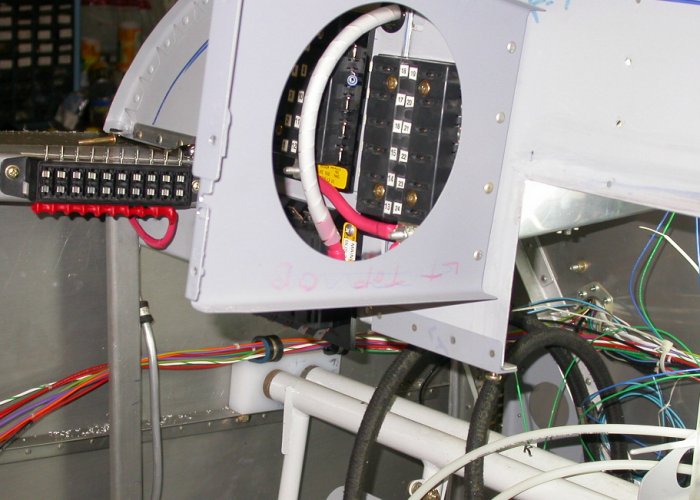 Routing the wire bundle aft past the rudder pedals and through the
fuselage frame (I forget the proper terminology for that piece).
Also shows relationship of the 3 main fuse blocks and the E-bus fuse
block. Also shows the reinstalled fuel tank vent.
Routing the wire bundle aft past the rudder pedals and through the
fuselage frame (I forget the proper terminology for that piece).
Also shows relationship of the 3 main fuse blocks and the E-bus fuse
block. Also shows the reinstalled fuel tank vent.
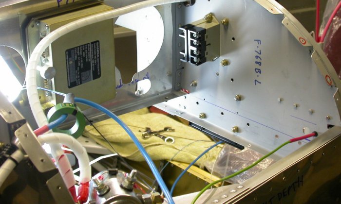 Opposite view of subpanel from previous picture. Shows installed Omron
relay mounted to the back of one of the main fuse blocks (and using same
hardware) and the GRT HE sensor still waiting to be installed onto the blue
alternator B lead. I've emailed GRT 3 times in the last 10 days and
STILL waiting for them to answer a question so I can finish the installation
of the alt B lead and the current sensor.
Opposite view of subpanel from previous picture. Shows installed Omron
relay mounted to the back of one of the main fuse blocks (and using same
hardware) and the GRT HE sensor still waiting to be installed onto the blue
alternator B lead. I've emailed GRT 3 times in the last 10 days and
STILL waiting for them to answer a question so I can finish the installation
of the alt B lead and the current sensor.
Oct 19 - lay out and drill holes for snap bushings for 3 main battery wires. Calculate what additional wire & related protection supplies I'll need for the battery wires. Plan for additional needs for wires going aft; all 3 magnetometers and the BMA A/P servo. Lay out additional snap bushing holes all the way back to battery area behind LT baggage compartment. 1.5 hr
 Shows reinstalled LT fuel tank vent, 3 bushings for the 3 main battery leads
coming forward from the batteries. Ground plate in background.
Adel clamps are mounted to the 2 bolts holding down the rudder pedals.
Shows reinstalled LT fuel tank vent, 3 bushings for the 3 main battery leads
coming forward from the batteries. Ground plate in background.
Adel clamps are mounted to the 2 bolts holding down the rudder pedals.
Oct 20 - Received and put away Allied switches order. Work on switches layout. Decided on 1" spacing. Work on updating switches drawing and setting it up as life-size. Update web site 2.75 hr + 1.0 hr doc
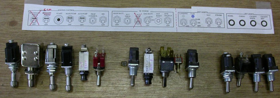 This is the initial layout of all the switches. They will go on a
switches panel below the main instrument panel. Doing this showed me I
will need a 1" spacing for the switches.
This is the initial layout of all the switches. They will go on a
switches panel below the main instrument panel. Doing this showed me I
will need a 1" spacing for the switches.
Oct 21 - print out new switches drawing. Received ACS order of hardware and AN910 unions. Lay out and drill a couple switches holes. NOTE: 1/2" hole is a bit too big to use for the toggle switches; 15/32" is much better. 1.0 hr
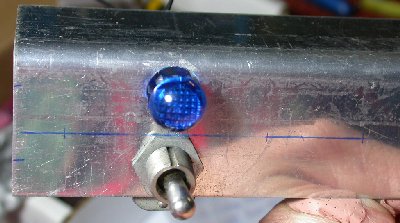 Here is the start of laying out and drilling the holes for the light
switches. This wig-wag taxi light switch is the trickiest one to fit,
because it uses the flashing indicator bulb as
part of the flasher circuit. So,
the switch is mounted below the mount line and the indicator is mounted
above it. I'm not yet sure where I will fit in any legends for this
combination. Landing light is not on wig-wag, and goes to the left of
the taxi light. The metal is the standard 12" long 1.5" x 1.5" 0.063"
2024T3 angle from ACS.
Here is the start of laying out and drilling the holes for the light
switches. This wig-wag taxi light switch is the trickiest one to fit,
because it uses the flashing indicator bulb as
part of the flasher circuit. So,
the switch is mounted below the mount line and the indicator is mounted
above it. I'm not yet sure where I will fit in any legends for this
combination. Landing light is not on wig-wag, and goes to the left of
the taxi light. The metal is the standard 12" long 1.5" x 1.5" 0.063"
2024T3 angle from ACS.
Oct 22 - adjust and reprint switches layout drawing. Lay out switches and indicators. Test LEDs from Allied order. Called GRT to try to get an answer to my question about the GRT Hall Effect sensor mounting. 1.0 hr
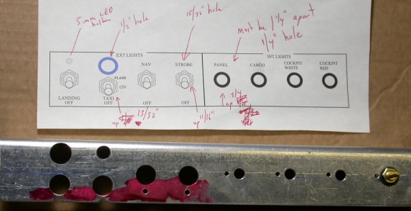 Here, I've laid out & drilled all the holes for the lighting switches and
dimmers. I swapped the landing & taxi light switch locations to give
me more room for labeling the switch positions.
Here, I've laid out & drilled all the holes for the lighting switches and
dimmers. I swapped the landing & taxi light switch locations to give
me more room for labeling the switch positions.
Oct 24 - received Perihelion order of 2 Power Schottky diodes. Also got call from Sandy at GRT, and she tells me I can place the GRT Hall Effect sensor near wires OUTside the sensor without affecting the current reading of wires INside the sensor. Between these electrical things and the engine oil cooler hoses, looks like I have plenty of work to do. Laid out Power Schottky diodes. Realized the heatsinks for the diodes are attached to the base of the diode, which is the cathode(or maybe anode - I always forget which is which). That means the heatsink will have +12v on it and will always be electrically "hot". That is not good, and I can't coat it with liquid electrical tape, as that will negate the purpose of the heatsink. Maybe I can make a perforated plexiglas or fiberglass cover to go over it. Laid out and drilled holes for lighting switches. Had to do it a couple times before I was satisfied with results. Switched taxi and landing light switch locations, so there's more room for the 3 switch position legends for the taxi light. Update web site 2.5 hr + 0.5 hr doc
Oct 25 - emailed Eric Jones about how to deal with electrically hot heatsinks. Eric says to ask AeroElectric list about it. Asked AeroElectric list.
Oct 26 - AeroElectric list says the diodes should have an electrical insulator between the diode and the heatsink, so the heatsink isn't hot. Odd that Eric didn't already do that. Anyway, now I will look into modifying Eric's Power Schottky packages so the heatsink is thermally connected to the diode, but electrically isolated. Emailed Eric about it. In the evening, worked on modifying the Schottky packages. Added a 1/16" length of heatshrink to the mount studs, to insulate the heatsink from the studs and enlarged the stud holes in the heatsink. That seemed to work pretty well, but then I noticed I still had intermittent shorting only after I fully tightened the mount nuts. Removed Schottky & heatsink, and made sure top of heatsink and bottom of Schottky were completely smooth and free of any sort of burrs. Still getting some shorts between case and heatsink. Maybe the pad is just for transferring heat, but not for insulating electrically. Will email Eric about it. 2.0 hr
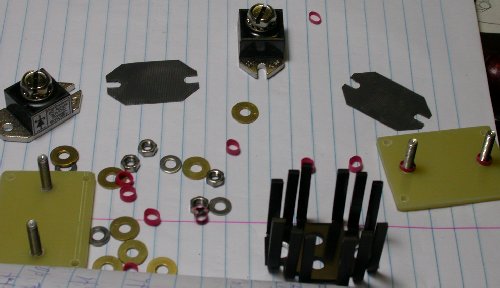 Perihelion Power Schottky all dismantled to isolate the heatsink from the
base. The little red things are 1/16" long pieces of heatshrink to
isolate the heatsink from the mount studs.
Perihelion Power Schottky all dismantled to isolate the heatsink from the
base. The little red things are 1/16" long pieces of heatshrink to
isolate the heatsink from the mount studs.
 Here's the heatsink mounted on the fiber base, with the holes enlarged and
the heatshrink
insulators in place.
Here's the heatsink mounted on the fiber base, with the holes enlarged and
the heatshrink
insulators in place.
 I was still getting some shorting after all the above, so I dismantled again
and removed small burrs from inner heatsink holes. Still didn't
resolve the issue, though. I also used a fine file to smooth the
bottom of the diode case, but still getting shorting. It must be that
the pad is a heat conductor, but not an electrical insulator.
I was still getting some shorting after all the above, so I dismantled again
and removed small burrs from inner heatsink holes. Still didn't
resolve the issue, though. I also used a fine file to smooth the
bottom of the diode case, but still getting shorting. It must be that
the pad is a heat conductor, but not an electrical insulator.
Oct 27 - Emailed Eric at Perihelion about my observations from last night's work. Eric said to ship him the Schottky diodes and he would make sure they were fully and properly electrically isolated from the heatsink. Very nice of him. Packed & shipped diodes to Eric. Trim ends of lighting switch panel. Update web site 0.25 hr + 1.0 hr doc
Oct 28 - Lay out and drill engine & battery switch panel. Install GRT Hall Effect current sensor and alternator Battery cable. Decided to move starter switch up on the engine/battery switch panel. Make and rivet backing plate for that. Fill old hole with JB Weld. 5.5 hr
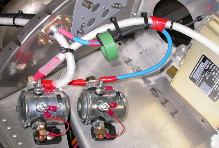 Here is the GRT Hall Effect current sensor and alternator Battery wire (blue
wire) installed. Main contactor on LT, engine bus contactor on
removable panel on RT.
The wires from the current sensor are going through small snap bushing in
the F745 panel on the right. They are encased in heatshrink.
Here is the GRT Hall Effect current sensor and alternator Battery wire (blue
wire) installed. Main contactor on LT, engine bus contactor on
removable panel on RT.
The wires from the current sensor are going through small snap bushing in
the F745 panel on the right. They are encased in heatshrink.
 Here, I have decided to move the starter switch up, so it is centered on the
small hole. I made a 1" x 1.5" backing plate and riveted it over the
old hole. I decided it was quicker and easier to patch and redrill
this hole than to redo the entire switch panel.
Here, I have decided to move the starter switch up, so it is centered on the
small hole. I made a 1" x 1.5" backing plate and riveted it over the
old hole. I decided it was quicker and easier to patch and redrill
this hole than to redo the entire switch panel.
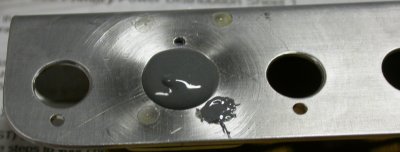 Then I filled the old patched hole with JB Weld. The countersink
scratched up the metal around the lower RT rivet hole some, so I put a bit
of JB Weld there, too.
Then I filled the old patched hole with JB Weld. The countersink
scratched up the metal around the lower RT rivet hole some, so I put a bit
of JB Weld there, too.
Oct 29 - Mill the JB Weld down flush with rest of panel, mill one rivet shop head, fill pinholes in JB Weld. File it smooth and flat. Route and protect current sensor wires to EIS. Install Adel clamps for EIS harness. Trim, label, and crimp DB sockets onto EIS harness wires. 4.0 hr
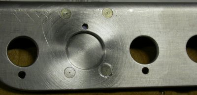
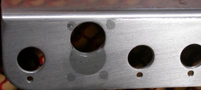 After milling the JB Weld down flush with the sheet metal and filing it
smooth, I redrilled the hole where I wanted it. The hole is cutting a
bit into the upper LT rivet head, but no big deal in this application.
On the back side, I also milled away part of the shop head for that rivet,
so the hold-down nut on the back will clear it. This will all be
painted flat black when I am done with it.
After milling the JB Weld down flush with the sheet metal and filing it
smooth, I redrilled the hole where I wanted it. The hole is cutting a
bit into the upper LT rivet head, but no big deal in this application.
On the back side, I also milled away part of the shop head for that rivet,
so the hold-down nut on the back will clear it. This will all be
painted flat black when I am done with it.
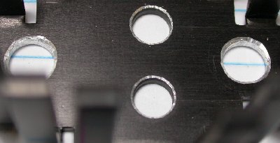
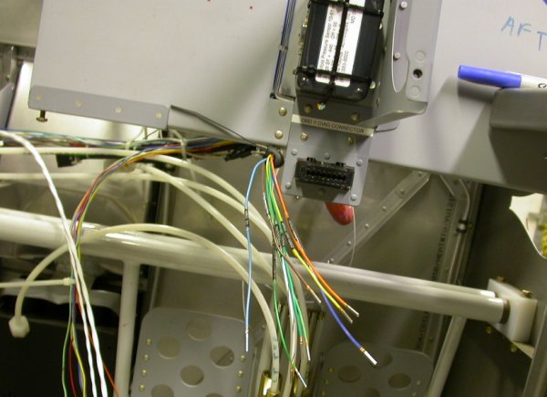 The bundle of wires going to the EIS is growing. Each wire is labeled
and has its machined socket crimped on. Above the EIS wires is the ODB
diagnostics connector and above that is the GRT MAP sensor box.
The bundle of wires going to the EIS is growing. Each wire is labeled
and has its machined socket crimped on. Above the EIS wires is the ODB
diagnostics connector and above that is the GRT MAP sensor box.
Oct 30 - Look at mounting options for Perihelion over and under voltage protection modules. They are so small, I can stick them just about anywhere when I am ready for them; not an issue. Update web site 0.25 hr + 1.0 hr doc
Oct 31 - Emailed Eric at Perihelion with questions about the external warning LEDs for his overvoltage and low voltage protection modules. He replied promptly that the circuits are already set up internally for the LEDs, so no external series resistors or forward voltage calculations are needed for the external warning LED for each module. Eric's customer support has been outstanding. Wired up current sensor and EIS grounds. Redid the ground connectors I've made so far, and added labels to each. 1.0 hr
thus ends another month of work. Go to November, 2006 avionics/electrics.
BACK TO MY RV BUILDER'S HOME
BACK TO BRIAN'S HOME