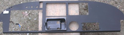
 Here is the instrument panel with everything removed for painting, and the
AirGizmos 496 adapter mounted into where the 530 tray goes. It's a
sloppy fit, height-wise, but it's supposedly a temporary arrangement.
Here is the instrument panel with everything removed for painting, and the
AirGizmos 496 adapter mounted into where the 530 tray goes. It's a
sloppy fit, height-wise, but it's supposedly a temporary arrangement.APRIL, 2007 AVIONICS, ELECTRICS, & CONTROLS
If it's general supporting wiring, it's on this page. If it's strictly engine wiring, it's on the engine page, so be sure to check there for details.
April 1 - modify Garmin GNS 530 tray mount bracket to accept the AirGizmos adapter for the Garmin 496. I won't buy the 530 until I am ready for IFR training, so I am just having Eckhard wire up the 530 tray, then I will remove the tray and put the 496 in that slot until I am ready for the 530. Reassemble instrument panel and indicators. Start wiring indicators. 3.25 hr
Here is the instrument panel with everything removed for painting, and the
AirGizmos 496 adapter mounted into where the 530 tray goes. It's a
sloppy fit, height-wise, but it's supposedly a temporary arrangement.
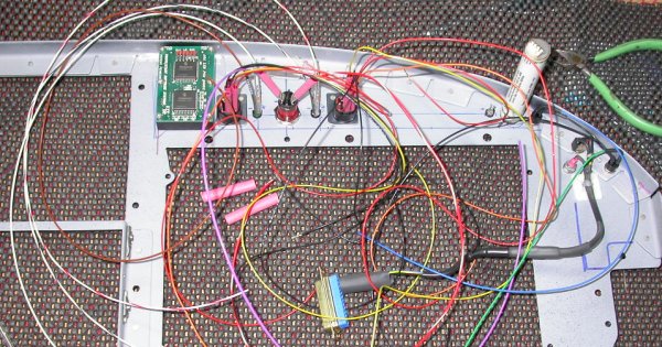 Here, I am wiring up all the warning indicators. All but the AoA
display will go to the DB-25 connector, to allow for quick & easy removal of
the panel. As the number of wires grows, I may need to use a DB-37
instead of the DB-25. I'm not putting the AoA display wires through
the DB connector, because the AoA display wires are all one shielded bundle
that I don't want to interrupt, and because the display already has a quick
disconnect connector.
Here, I am wiring up all the warning indicators. All but the AoA
display will go to the DB-25 connector, to allow for quick & easy removal of
the panel. As the number of wires grows, I may need to use a DB-37
instead of the DB-25. I'm not putting the AoA display wires through
the DB connector, because the AoA display wires are all one shielded bundle
that I don't want to interrupt, and because the display already has a quick
disconnect connector.
April 2 - ordered special small heat gun, like Eckhard's, for shrinking tubing in tight places. It's a Weller model 6966C. I really need it for shrinking the tubing on the indicators without spraying heat all over and melting the plastic items. By far the best price I found was at All-Spec. It was $20-30 less there than anywhere else. They were rather mysterious about shipping charges, though, so I hope they don't screw me and make up the difference in inflated shipping charges. Finished wiring indicators, wired power & ground for low fuel indicators. Update web site 1.0 hr + 1.5 hr doc
April 3 - ordered the high end Daniels crimper, shielded wire, pins & sockets, etc from SteinAir. Got my invoice from All-Spec; shipping was $10, so that's fairly reasonable. Hope I get the heat gun soon, as my indicators wiring is waiting on it.
April 6 - Received new Weller 6966C heat gun - it is SUPER. Shrink tubing for indicators wiring. Route, label, and secure indicator wires. Install all displays and Garmin trays. 6.5 hr
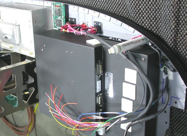 Here, the wiring for the panel warning indicators is organized and mostly
secured.
Here, the wiring for the panel warning indicators is organized and mostly
secured.
April 8 - Make 14" #1 Phillips screwdriver, needed for Garmin trays. Install Garmin tray backs. Secure indicators wiring. Crimp sockets onto indicators wires. 4.5 hr
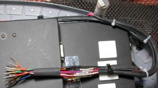 This is the indicators wiring, with crimped machined gold sockets, ready to be
installed into a DB connector.
This is the indicators wiring, with crimped machined gold sockets, ready to be
installed into a DB connector.
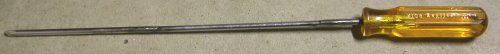 I made one 14" long #1 Philips screwdriver by welding together one good 10"
screwdriver and the shank from another 10" screwdriver with a worn-out tip.
This lets me easily get to the back of the Garmin trays, to fasten the
backplates.
I made one 14" long #1 Philips screwdriver by welding together one good 10"
screwdriver and the shank from another 10" screwdriver with a worn-out tip.
This lets me easily get to the back of the Garmin trays, to fasten the
backplates.
April 9 - label remaining indicators wires, plug indicators wires into DB-25 connector, document wiring for this connector. D-sub shells I have won't fit my Amp/Tyco D-sub connectors. 1.5 hr + 1.0 hr doc
April 10 - received SteinAir order. Ordered more Tyco MIL-spec D-sub connectors and shells from Allied.
April 11 - didn't work on plane last night - EAA 740 meeting & working on EAA newsletter. Spent a couple hours with TurboCAD, updating electrical drawings. In evening, worked on panel wiring. I'm getting confused about some of the interconnections, so I will email some questions. 3.0 hr + 2.0 hr doc
April 12 - got some good info from Grand Rapids' downloads page, particularly the one called "Interface Diagram GNS430/530 SL30". Also got several good reply emails. Studied GRT. BMA, Garmin interconnections docs. Have a much better overall interconnections understanding now. 2.0 hr
April 13 - John Moody sent me a spreadsheet with his avionics interconnections on it. He recommended that I draw out all my avionics wiring interconnections before doing any actual wiring. Makes sense. So, I am working on that now, in both text and spreadsheet modes. 2.0 hr
April 16 - Been working 7x24 over the weekend on data corruption issues at work. Spent a couple hours updating my wiring interconnections document. Received my Allied order of MIL-spec D-sub connectors and shells. I'd ordered the metal shells, but they are incredibly HEAVY, and will have to go back. 2.0 hr
April 17 - organizing & updating wiring interconnections doc 2.0 hr
April 18 - updating wiring interconnections doc. I've also resumed setting up my supercharger wastegate control. 1.0 hr
April 19 - start rewiring starter circuit so it isn't on the main fuse blocks, controlled by the main contactor. This way, I can use the main contactor as an avionics master, and I won't need the main contactor energized during startup. Bought a heavy duty sealed inline fuse holder, and started installing that. 1.0 hr
April 20 - mount inline fuse for starter solenoid circuit. Sent metal D-sub shells back to Allied; they are so heavy, the USPS cheapest shipping was $10. 0.5 hr
April 22 - after getting the starter solenoid all rewired so cleverly, I suddenly realized this won't work, as the main circuit to the starter motor is still on the SWITCHED side of the main contactor. So, the solenoid will click closed when I press the starter button, but there will be no power available for the solenoid to switch to the starter motor, until I close the main contactor. I'll either have to add an Avionics Master switch and contactor or move the heavy starter wire to the UNswitched side of the main contactor. Pondered the 2 choices, but no conclusion. 2.5 hr
April 23 - Pondering solution to above problem. Decided it's easiest, cheapest, lightest, and quickest to move the main starter cable to the unswitched side of the main contactor. Rewired and re-secured starter wire. After completing it, I am still having second thoughts about doing it that way. I know of no one's electrical drawings that don't show the starter wire on the switched side of the main contactor. I'm not sure why everyone has it that way, but I really can't see a problem with it the way I've done it. It does lengthen the "hot" cable attached to the battery, but it's already pretty long, just getting from the aft batteries to the contactors. It does make the cable going through the firewall always hot. I'm just not sure what would be gained by having the main contactor in series with two other contactors; the starter solenoid and the Avionics Master. I'll let it ride like this for now, but I may switch it back and add an Avionics Master switch and contactor later. Ordered new AMP/Tyco D-sub shells from Allied, in plated plastic this time. 2.25 hr
April 24 - organize some of my documentation, build a new foldup table. Nothing really accomplished. 1.0 hr
April 25 - Spent a couple hours further updating my interconnections doc and GRT-Garmin interconnections doc. I got the reamer I needed, so I'm also back to working on the supercharger wastegate. Update web site 2.0 hr + 1.0 hr doc
April 27 - received Allied DB shells reorder. Put away shells, organize DB shells, connectors, pins, hardware. Wire up low fuel pressure warning circuit between Gems switch and panel indicator. Grind more metal off removable electrics tray for better fit. Cleaned up shop around back door and rearranged some completed plane parts. Tripped while carrying instrument panel (with about $30K of instruments in it) and fell onto it on the concrete. Bent panel upper support angle a bit, but no apparent damage to panel displays. 2.5 hr
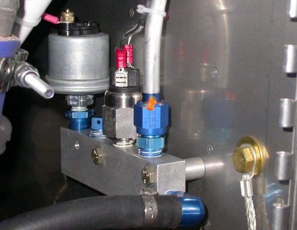 Here is the fuel pressure distribution block, fully wired.
April 28 - resume wiring low fuel pressure circuit. Install instrument panel and batteries in prep for another engine run. Start wiring up additional warning circuits. I realized my scheme to rewire the starter solenoid isn't going to work well, because now I can never use both batteries to start the engine. So, I decided I will be adding a separate Avionics Master switch and contactor. Several warning displays are not working right, so I spent some time troubleshooting them. The EIS warning light worked about 3 seconds, then died. I determined that the cheap Radio Shack indicator (RS p/n 272-336) had died. Fortunately, I already had 2 spares, so I swapped that out. My low fuel indicators wouldn't test, but I figured out I hadn't yet wired the grounds for that, so I did it. Fixed all wiring problems and all indicators are now OK. Started working on low coolant indicator wiring (to 0300). 8.0 hr
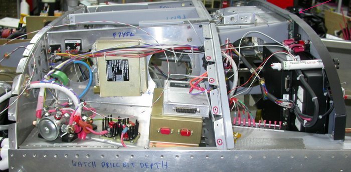 Here are all the panel and DC power control components and wiring.
Faint red arrow showing the bump in the top support angle on the instrument
panel. This is from when I tripped carrying this panel and smashed it
and myself into the concrete floor, face-first. Much cursing
then, I can assure you. No apparent damage to electronics. The
panel now has a slight bend in it where this bump is. I will
straighten it out with my Vise-grips seamer when I get a chance.
Here are all the panel and DC power control components and wiring.
Faint red arrow showing the bump in the top support angle on the instrument
panel. This is from when I tripped carrying this panel and smashed it
and myself into the concrete floor, face-first. Much cursing
then, I can assure you. No apparent damage to electronics. The
panel now has a slight bend in it where this bump is. I will
straighten it out with my Vise-grips seamer when I get a chance.
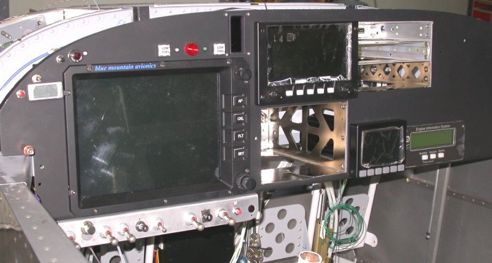 Here is the installed instrument panel. Not complete, but getting
there. You can see the bump in the tweaked upper angle, just above the
AoA indicator. One end of the panel must have hit the floor first when
I tripped, then I fell into the panel while still holding both ends, causing
the panel to bend some. The panel is now just slightly off from being
perfectly straight across. No damage to the knobs or any of the
displays. Perhaps it helped that I never let go of the panel
when I fell.
Here is the installed instrument panel. Not complete, but getting
there. You can see the bump in the tweaked upper angle, just above the
AoA indicator. One end of the panel must have hit the floor first when
I tripped, then I fell into the panel while still holding both ends, causing
the panel to bend some. The panel is now just slightly off from being
perfectly straight across. No damage to the knobs or any of the
displays. Perhaps it helped that I never let go of the panel
when I fell.
April 29 - finish wiring low coolant warning circuit. Do another engine test run. Install supercharger pressure sender. Install and secure SC pressure wiring. Set up and document SC pressure EIS settings (AUX2) to 0245. 7.0 hr
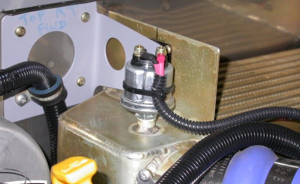 The supercharger pressure sensor is all installed and wired. It took a
lot of time to do this, because I had to tear into the existing cross-engine
wiring harness and add these 2 wires. Also, once I was aft of the
firewall, I had to tee the hot line, via a resistor, into a tee in the +4.8v
output line from the EIS to the Hall Effect current sensor, which took a lot
more time.
The supercharger pressure sensor is all installed and wired. It took a
lot of time to do this, because I had to tear into the existing cross-engine
wiring harness and add these 2 wires. Also, once I was aft of the
firewall, I had to tee the hot line, via a resistor, into a tee in the +4.8v
output line from the EIS to the Hall Effect current sensor, which took a lot
more time.
April 30 - inventory & organize switches; looking to see if I need to buy a new switch for new Avionics Master circuit I plan to add. I ran the engine awhile, and tweaked the EIS AUX2 offset value so it reads supercharger pressure accurately (2OFF=0). I also tried all 3 EIS tach P/R settings while the engine was running: 1 (as per EIS manual) = 2400, 2 (as per Tom Moore doc) = 1200, 3 = 800. No way is it idling at 2400. I doubt very much it's idling at 1200. I think the "3" setting seems to be the most accurate. I haven't tried "4" yet, but it could be that (600 rpm). I posted a question to the STi list about what EIS setting I should use. Start looking at GRT EFIS wiring. Update web site 1.75 hr + 1.0 hr doc
GO TO MAY, 2007 AVIONICS
BACK TO MY RV BUILDER'S HOME
BACK TO BRIAN'S HOME