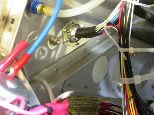
 Here is the LT side firewall eyeball pass-through fitting all done. Up
is to LT in pic. You can see the grounds terminal block at the bottom
of the pic. It's starting to fill up.
Here is the LT side firewall eyeball pass-through fitting all done. Up
is to LT in pic. You can see the grounds terminal block at the bottom
of the pic. It's starting to fill up.MAY, 2007 AVIONICS, ELECTRICS, & CONTROLS
If it's general supporting wiring, it's on this page. If it's strictly engine wiring, it's on the engine page, so be sure to check there for details. By now, after 2 years of work, I am pretty much finished with wiring this disastrous engine.
May 1 - worked to 0200 on Grand Rapids Horizon EFIS/AHRS wiring. 2.0 hr
May 2 - work on avionics interconnections doc 3.0 hr
May 3 - more updating the avionics interconnections doc 3.0 hr
May 4 - work on Grand Rapids EFIS and AHRS wiring. Reading the Sandia manual tells me of one switch and two lights I will need to add to panel to use their AIM (Altitude In-flight Monitoring) feature. Unexpected things like this are why I left as much spare room as possible on panel. 0.75 hr
May 5 - more GRT EFIS/AHRS wiring. Power, ground, serial connections all set up OK. It looks like the EFIS engine page will need some setup work, though. 1.75 hr
May 6 - work on GRT magnetometer wiring. Spent some time pondering the wire run for the magnetometers. Best in planned tail location or in wing? Cleanest, safest way to route the wires through and aft of the main spar? Interference with wing spar? Better to wait until wing is installed? Much to ponder. Ran GRT mag wires to just fwd of main spar, then coiled them up for more decisions later. Started installing Blue Mountain EFIS cables & wires. 3.0 hr
May 7 - received B&C order of new contactor. Rewired DC control circuits to put starter solenoid back to the SWITCHED side of the main contactor, where it was before I moved it, and to add an Avionics Master contactor. Removed BMA CPU and removable electrics tray, so I can get access to properly route and connect all the grounds I've wired lately. It's difficult to get at the ground plate with the removable electrics tray in place. Worked to 0145. 1.25 hr
May 10 - been kinda busy lately dealing with beginning my hangar construction, and trips out to the airport to see how that's coming along. Finished installing ground wires. Wrapped LT wire bundle through firewall with cold shrink tape, and measured it (9/16") for the eyeball fitting. 1.0 hr
May 12 - finish drilling eyeball fitting to 9/16". Ream eyeball a bit more to fit wire harness. Secure wiring through firewall. Secure MT prop controller and engine LT wiring. Clean up. Start installing avionics master switch. Wire BMA power. 4.5 hr
Here is the LT side firewall eyeball pass-through fitting all done. Up
is to LT in pic. You can see the grounds terminal block at the bottom
of the pic. It's starting to fill up.
May 13 - Wire Avionics Master switch. Tweak & secure wiring harness. Make cable to go from main contactor (at aux) to avionics master contactor. Reinstall removable DC control tray and wire avionics master switch and contactor. Secure all. Cleanup. Straighten bent instrument panel top angle. Make a pass-through for Garmin stack wiring, so panel can come in and out without affecting Garmin stack inter-wiring. Glue grommet for pass-thru. Trying to decide if I should mount the BMA CF card reader in the plane or leave it out and just hook it up when I need to use it. It'd be more convenient if it was installed, but do I want to take up the space and weight (and time installing) for something I will only use once a month at the most? 6.25 hr
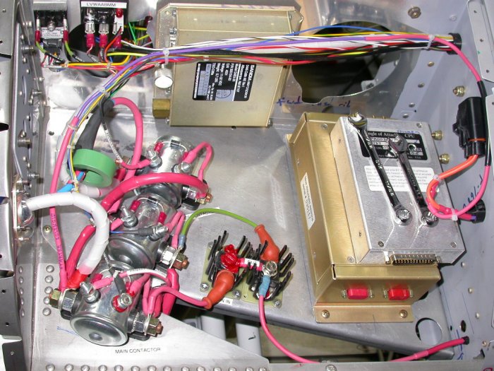 With the addition of the Avionics Master contactor, the removable electrics
tray is starting to fill up. View is from LT side, with firewall on LT
edge of pic and subpanel on RT edge of pic. To remove the tray, the LT
edge (fwd) is tipped up as far as possible, then the RT (aft) edge will tip
down and slide out under the subpanel and panel.
With the addition of the Avionics Master contactor, the removable electrics
tray is starting to fill up. View is from LT side, with firewall on LT
edge of pic and subpanel on RT edge of pic. To remove the tray, the LT
edge (fwd) is tipped up as far as possible, then the RT (aft) edge will tip
down and slide out under the subpanel and panel.
May 14 - Clean up shop. Rebuild an old portable air tank. Reinstall instrument panel & related connectors. Power up all & test new Avionics Master circuit - all good. GRT EFIS needs configuration work for sure - GBT (Gear Box Temp) shows up on EFIS engine page as "amps". BMA EFIS up OK. Both GRT and BMA EFIS basic function test OK. Update web site 2.0 hr + 1.0 hr doc
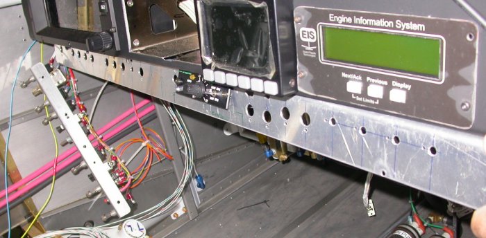
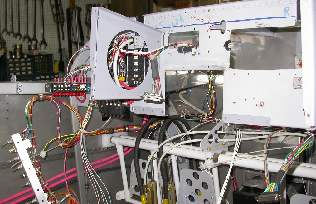 Here is overview of some of the panel wiring. GRT EIS connector is in
lower RT. Removable switches panel in lower LT. Always-hot E-bus on
LT, fuse blocks to RT of that. Click on pic for larger view. I am
using the rectangular cutout I had erroneously made for the GRT ARINC-429
mounting to pass wires through the subpanel (upper center of pic). The subpanel cutout on the
upper RT is for the Garmin trays. Because the lower 2 Garmin trays
protrude through the subpanel and the audio panel does not, I needed a passthru
cutout so I could slide the panel in and out without the subpanel interfering
with the wires between the transponder/SL-30 and the audio panel. So, I cut a half
circle in the side of the Garmin tray cutout in the subpanel, and glued in a
rubber grommet. After the RTV had cured, I cut half of it off, so
the wires can slide in and out.
Here is overview of some of the panel wiring. GRT EIS connector is in
lower RT. Removable switches panel in lower LT. Always-hot E-bus on
LT, fuse blocks to RT of that. Click on pic for larger view. I am
using the rectangular cutout I had erroneously made for the GRT ARINC-429
mounting to pass wires through the subpanel (upper center of pic). The subpanel cutout on the
upper RT is for the Garmin trays. Because the lower 2 Garmin trays
protrude through the subpanel and the audio panel does not, I needed a passthru
cutout so I could slide the panel in and out without the subpanel interfering
with the wires between the transponder/SL-30 and the audio panel. So, I cut a half
circle in the side of the Garmin tray cutout in the subpanel, and glued in a
rubber grommet. After the RTV had cured, I cut half of it off, so
the wires can slide in and out.
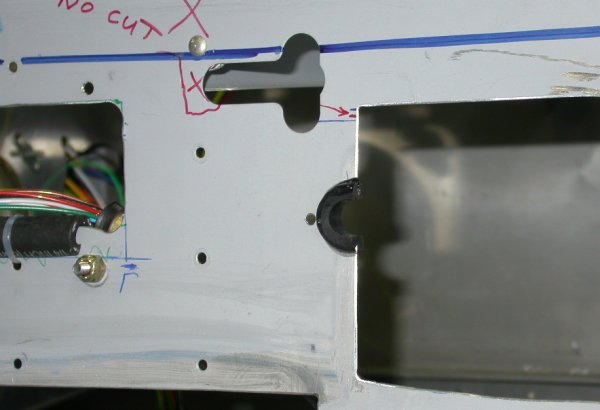 Here is a closeup of the cutout I had to do to keep the Garmin stack
interconnect wires from interfering with being able to slide the panel in
and out. It's a half-circle, protected by a glued-in rubber grommet.
On RT side of pic is wires passing thru cutout I'd erroneously made for the
GRT ARINC-429 module. Wires are secured with Adel clamp and protected
by split rubber hose tie-wrapped to edge of metal.
Here is a closeup of the cutout I had to do to keep the Garmin stack
interconnect wires from interfering with being able to slide the panel in
and out. It's a half-circle, protected by a glued-in rubber grommet.
On RT side of pic is wires passing thru cutout I'd erroneously made for the
GRT ARINC-429 module. Wires are secured with Adel clamp and protected
by split rubber hose tie-wrapped to edge of metal.
May 15 - plan, connect, secure Blue Mountain EFIS/CPU interconnect cables. 1.0 hr
May 17 - route & secure BMA cables 1.0 hr
May 18 - update avionics/electrics docs, start making an avionics block diagram 1.0 hr
May 19 - BMA wiring. Wasted time going to Staples & Radio Shack looking for a longer standard PC serial cable than the short one that came with the Blue Mountain for the magnetometer. They didn't have diddly. Will have to order one from the Internet. I did buy an RJ45 crimper and connectors. Practiced with that awhile and then made a new Ethernet cable to go from the BMA CPU to the BMA Autopilot (only needed one 7" long). 5.25 hr
May 20 - more work on BMA wiring. LOTS of pondering about where to put the autopilot breaker. I really NEED an A/P breaker, not just a fuse; in case the A/P disconnect fails. I forgot to include it in my switches panel design. I am considering redoing the entire switches panel. I had been limited to 12" long sections before, because that's how long the 1.5" x 1.5" angles from ACS were. I now need to add another panel to hold the autopilot breaker, and it will look dumb as hell to add another 2" long switches subpanel in the gap between the existing switches subpanel and the center console/MT prop control mount bracket. Perhaps I can just order a new instrument panel from Van's, cut the bottom 2" off that, and mount it upside down under my panel. The only problem is I already have a LOT of work into the existing switches panels. But I don't want my switches to look like a hack job, which is what I'll have if I try to add piecemeal another short switches subpanel. Also spent time looking at the connections from the SL30 and both the BMA and GRT EFISs. Formed a bunch of avionics questions to ask tomorrow on the Internet. 6.0 hr
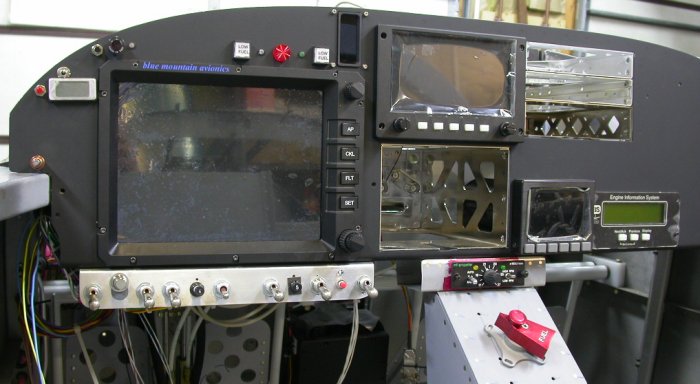 Here is the panel in place, with the main switches subpanel and the console
with MT prop controller in place. The gap is bad enough.
Patching in a little angle to add the A/P breaker will be even worse.
I'd been restricted to using just 12" lengths of the 1.5" x 1.5" angle, cuz
that's how ACS sells it. I will redo it right, with just one piece all
the way across, accommodating all my switches needs, as well as taking care
of the MT prop controller mount. This will also let me make the
subpanel dropdown a bit more than 1.5", as teh 1.5" was quite marginal and I
was wondering how I was going ot squeeze switch labels in there, especially
where there is a switch and an indicator together. Having 2" to play
with should be MUCH better, and then I can add more switches easily, as
needed.
Here is the panel in place, with the main switches subpanel and the console
with MT prop controller in place. The gap is bad enough.
Patching in a little angle to add the A/P breaker will be even worse.
I'd been restricted to using just 12" lengths of the 1.5" x 1.5" angle, cuz
that's how ACS sells it. I will redo it right, with just one piece all
the way across, accommodating all my switches needs, as well as taking care
of the MT prop controller mount. This will also let me make the
subpanel dropdown a bit more than 1.5", as teh 1.5" was quite marginal and I
was wondering how I was going ot squeeze switch labels in there, especially
where there is a switch and an indicator together. Having 2" to play
with should be MUCH better, and then I can add more switches easily, as
needed.
May 21 - Put an ad up on the VAF and Matronics sites for someone with a messed up RV7 panel I could get cheap, rather than buying a new one from Van's just to cut it up. I got several prompt replies, including one from SteinAir to send me one just for the cost of shipping. I could have just ordered a sheet of 0.063" from ACS, but that would have cost a lot, plus a lot of shipping, plus I'd have to cut and bend it, and I don't think my shear will handle something that wide, although I think the brake might barely handle it. Anyway, just cutting the bottom off an instrument panel and using it upside down as a switches subpanel seems like the way to go, and I can't beat the deal SteinAir offered me. That's very nice of them. Their customer service is always so personal and outstanding. Also ordered a 25' serial cable with DB9 connectors (will cut one off to thread it through the plane) and the A/P 10a breaker from ACS. Also talked to Reinhard Metz at A&T Labs. He makes the K-11 dimmer system sold through ACS. ACS was out of stock and couldn't answer some of my questions about it, so I talked to Reinhard about it & ordered it from him. I hadn't planned on needing a dimmer bus, as my lighting already has individual dimmers from Perihelion. But the avionics wiring is calling for leads to the dimmer bus, so I am going to add one. Yet another reason to redo the switches subpanel, to add that. Worked on avionics docs 1/2 hr. Update web site 0.5 hr + 1.0 hr doc
May 22 - convert indicators wiring connectors from DB25 to DB37. All 25 pins were used up and I need to add half a dozen more wires for the Sandia AIM (altitude warning) function. 1.0 hr
May 25 - update connector pinouts doc, organize docs. Received ACS order, 25' PC serial cable for BMA mag, and new instrument panel from SteinAir. Plan cut for panel and layout for MT prop controller in new switches subpanel I will make from this panel. Will have to wait until Tuesday over the long weekend to get the panel cut, as my shear isn't quite big enough to handle the full length of the panel. Tested indicators connectors OK. Tested serial cable with BMA magneto OK. 2.5 hr
May 27 - make bracket to support back of MT prop controller with new switches subpanel. Start making list of new things to add to switches subpanel; Dynon PC interface, Sandia PC interface, two DC jacks, dimmer bus switch. After making MT support bracket, I'm not sure if I'll need it, after all. Lay out switches subpanel cutout for MT prop controller. Lay out new subpanel for switches. Drill new subpanel, fit switches, fit anti-rotation washers. Plan main cut across panel to make it into a switches subpanel. Move MT prop controller hole layout for more metal between controller cutout and center console cutout. Cut out MT prop controller hole. 9.0 hr
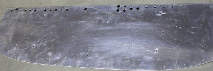 Here is the instrument panel I got from SteinAir, after I drilled most of the holes
for the switches and anti-rotation washers. Since taking the
pic, I've also got most of the MT prop controller mount hole cut in the
center. This will be cut off to give me about 2" height.
Here is the instrument panel I got from SteinAir, after I drilled most of the holes
for the switches and anti-rotation washers. Since taking the
pic, I've also got most of the MT prop controller mount hole cut in the
center. This will be cut off to give me about 2" height.
May 30 - finally connected with sheet metal shop guy & got my panel cut on his large shear, to shear off the portion I will be using as a switches subpanel. Trim & debur switches subpanel. Finish hole for MT prop controller and fit controller to switches subpanel. Update web site. 1.75 hr + 1.0 hr doc
 Here is the new switches subpanel, with all the (current) switches holes
drilled and the MT prop controller installed into it. It's just being
held in place here by hand for now. The old main switches subpanel
dangles on LT side of pic. Next job will be to move all those switches
and wires over to this new switches subpanel. The center console will
fit into a yet-to-be-made cutout under the MT prop controller. This
will be much nicer than the previous hodge-podge design of several small
switches subpanels. Now, I'll also have plenty of room under the
switches for switch labels. With the old subpanels, made from standard
ACS 12" long
1.5" x 1.5" angle pieces, getting labels in was going to be tricky,
especially where I have a 3 position switch and/or an indicator above the
switch. I also need to cut off a couple of the pressed-in subpanel
mount studs on the bottom of the main panel, and mate the remaining ones to
this new subpanel.
Here is the new switches subpanel, with all the (current) switches holes
drilled and the MT prop controller installed into it. It's just being
held in place here by hand for now. The old main switches subpanel
dangles on LT side of pic. Next job will be to move all those switches
and wires over to this new switches subpanel. The center console will
fit into a yet-to-be-made cutout under the MT prop controller. This
will be much nicer than the previous hodge-podge design of several small
switches subpanels. Now, I'll also have plenty of room under the
switches for switch labels. With the old subpanels, made from standard
ACS 12" long
1.5" x 1.5" angle pieces, getting labels in was going to be tricky,
especially where I have a 3 position switch and/or an indicator above the
switch. I also need to cut off a couple of the pressed-in subpanel
mount studs on the bottom of the main panel, and mate the remaining ones to
this new subpanel.
May 31 - fit switches subpanel to panel. Cut off one captive stud and fit others to subpanel. Remove switches from old switches subpanel and install into new one. Add BMA A/P breaker (which was the original purpose of all this). 1.5 hr
GO TO JUNE, 2007 AVIONICS PAGE
BACK TO MY RV BUILDER'S HOME
BACK TO BRIAN'S HOME