 Here's the throttle quadrant top, back from engraving. I will mill out
the unused engraving in the middle.
Here's the throttle quadrant top, back from engraving. I will mill out
the unused engraving in the middle.ENGINE WORK March, 2007
If it's strictly engine wiring, it's on this page. If it's more general supporting wiring, it's on the avionics/electric page, so be sure to check there for details.
March 2 - I'm having a quite difficult time getting my questions on the STi list answered. I've repeated the questions 3 times. So, I'm just trying to figure things out on my own. I've run into this problem before, where I have to keep asking a question over and over and over before Jan or one of his people will answer it. I've figured out much of it on my own, and rephrased the remaining questions:
Is it a problem to have the initial idle speed 200 rpm higher with the supercharger connected than it was before the supercharger was connected?
Is there a way to control what the initial idle speed is at startup?
Is it a problem to have a wastegate that allows 7psi inlet pressure when open at a high idle speed, or should I replace it with a bigger one?
Is this inlet pressure a problem that I should solve by replacing the wastegate with a bigger one, or should I just ignore it & move on?
I'll probably end up just making my own decision. While, on one hand, I am starting to think the inlet pressure is something that I can live with and isn't hurting anything, I can also swap out the 1/2" ball valve for a 3/4" one without TOO much trouble. I'll have to mill off the old 1/2" threaded adapter and weld on a 3/4" one. I calculated that the a 3/4" hole will give me 225% of the vent area I have with the 1/2" hole. So, that would be a pretty good gain.
Placed orders for muffin fans and infrared thermostat, to aid in continued engine testing and EIS calibration. Received ACS and Avery orders.
March 3 - put away ACS and Avery orders. Clean up bench & reorganize. 1.5 hr
March 4 - go through Gary Newsted's discrepancy list. Set up OBD scanner tool. It won't scan the vehicle, though - it says the vehicle is not responding. I'll have to ask Eggenfellner and the AutoXray scanner people about this. Photograph and pack up SuperTrapp mufflers and related parts to sell on eBay. 2.25 hr
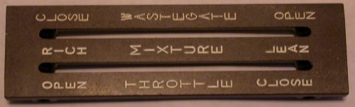
March 5 - Got my throttle quadrant top back from Dave Czachorowski at Full Throttle Concepts. While the engraving isn't quite as bold as the stock engraving, it looks like it'll get the job done. Mickey Coggins replied to my query about the OBD scanner not working. The OBD port gets its power from the ECM memory circuit, not from the ECM, as I'd assumed. I had pulled the ECM memory fuse, as I didn't see any need to keep the memory alive at this point. Later tested OBD scanner with the ECM memory fuse in place, and it worked fine. I noted 2 things, though; I am getting an unexpected ECM fault due to "no intake air temperature circuit", and the OBD scanner tells me the throttle moves from 17% to 78%, when it seem it should indicate from 0-100%. I know the throttle itself is correct. The Subaru manual says the intake air temp is part of the MAF sensor, which Jan removed. Supposedly we have an intake air temp sensor, but it doesn't seem to be working as such. The OBD scanner tells me the ECM thinks the inlet air temp is minus 40 degrees. Will ask about these things on the STi list. Machined obsolete lettering off the throttle quadrant top and installed it back into the quadrant. Still no answers to my questions on the STi list. 1.25 hr
Here's the throttle quadrant top, back from engraving. I will mill out
the unused engraving in the middle.
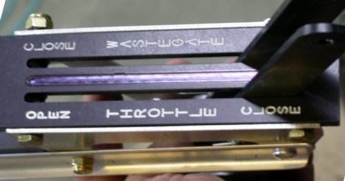 Throttle quadrant top, with the center lettering milled out, and reinstalled
into the quadrant.
Throttle quadrant top, with the center lettering milled out, and reinstalled
into the quadrant.
March 6 - Big blowup with Jan Eggenfellner again. He sent me an email and told me not to post links to my website in my replies to people's questions on his Yahoo group. Then he compounded that by jumping all over me because he'd just discovered that I'd changed the wastegate size. That shows how little attention he pays to the STi Yahoo support group list, as I've been talking on that list since about last June or July about redoing the wastegate, and I posted a notice there back in September describing what I'd done, complete with pictures. Anyway, he triumphantly exclaimed that everything was my fault for changing the wastegate diameter, and wouldn't answer any other questions. This is especially irritating, given that the wastegate came from Eggenfellner with NO supported way to activate or control it, and we've been totally on our own to come up with something.
Gary and I then had a good intelligent conversation about the wastegate. As Gary said, and as I've seen, the volume of air coming out of the supercharger, even at idle, is so high that the small leaking from the butterfly valve will be like a siphon hose at Niagara Falls. When I planned the wastegate I designed, I had no idea that there would be so much volume coming from the supercharger. So, I will be swapping back to the original wastegate as soon as possible. Fortunately, I bolted the cover over the old butterfly valve port, rather than welding it. I also received the infrared thermometer I ordered to use as a check on my engine temperature readings. Posted questions to STi list about throttle opening readings on the OBD scanner and about the intake air temperature issue.
March 7 - it was 20-25 degrees BELOW zero last night, so I didn't bother trying to heat up the garage and work out there. I got some good, prompt answers to my most recent questions on the STi list. Robert says the OBD throttle readout of 17-78% is normal and apparently means nothing. Jan says what we've been calling the inlet air sensor is in fact one that Eggenfellner substituted for the "and intake air temperature sensor" portion of the removed MAF sensor. Jan says it should work, so I will be troubleshooting that ASAP. I also finally got a good reply from Robert Paisley stating the same info as my conversation yesterday with Gary Newsted; that my wastegate is way too small for the volume of air, and I should return to the supplied butterfly valve wastegate.
March 8 - There was a flurry of concern about Jan's reply to me about the intake air temperature sensor wiring. Jan says the intake air temp probe non-ground wire goes to the brown wire on the MAF sensor connector, but that makes NO sense, as the MAF sensor connector isn't ATTACHED to anything. I decided to go home and work on the engine awhile, to get to the bottom of it. It's 10 degrees now. It was minus 10 last night, so I didn't do any work. To make a long story short, my 2 wires to the intake air temp sensor were reversed. I'm fairly sure that's how it came from the factory, but it doesn't matter now. Jan's reply about the air temp wires going to the MAF sensor connector threw everyone into a tizzy. I determined the MAF sensor connector was irrelevant to the intake air temp issue. Took the harness apart a bit, rewired the intake air temp sensor, and re-secured the wiring. 1.0 hr
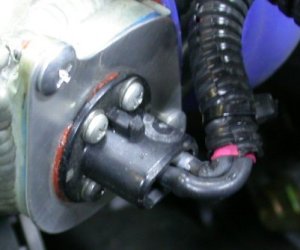 This is my intake air temperature sensor, as installed at the outlet of the
intercooler, where it will sample true intake air temp. The silver "G"
(for "Green" wire) is something I put there when I moved this sensor from
the RT radiator shroud to this location.
This is my intake air temperature sensor, as installed at the outlet of the
intercooler, where it will sample true intake air temp. The silver "G"
(for "Green" wire) is something I put there when I moved this sensor from
the RT radiator shroud to this location.
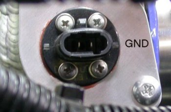 This pic shows how the STi intake air temp probe gets wired. On my
engine, brn/grn is ground and grn is signal. If you have different
color wires, just determine which is ground. Ground is the terminal on
the end with the deep orientation slot. It would have been better, for
a couple reasons, if this probe had come with the 2-pin connector that this
device was designed to mate with.
This pic shows how the STi intake air temp probe gets wired. On my
engine, brn/grn is ground and grn is signal. If you have different
color wires, just determine which is ground. Ground is the terminal on
the end with the deep orientation slot. It would have been better, for
a couple reasons, if this probe had come with the 2-pin connector that this
device was designed to mate with.
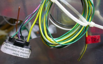 This is my unused MAF sensor connector and wiring. The "brown wire"
mentioned in Jan's reply came from the factory cut off to 2", as shown here.
Just for reference, this shows what wires are going to what pins on the
connector. The heavy YEL/GRN wire is power.
This is my unused MAF sensor connector and wiring. The "brown wire"
mentioned in Jan's reply came from the factory cut off to 2", as shown here.
Just for reference, this shows what wires are going to what pins on the
connector. The heavy YEL/GRN wire is power.
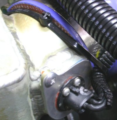 and here is the rewired intake air temp probe. I think it's very
important to secure those 2 slip-on terminals so they don't slip off.
To do that here, I have a 14" tiewrap around the intercooler outlet neck and
the wires. The wire end that had been marked with silver paint as "G"
is now on the OTHER terminal, and my OBD scan tool now sees the sensor OK
and gets seemingly accurate air temp info.
and here is the rewired intake air temp probe. I think it's very
important to secure those 2 slip-on terminals so they don't slip off.
To do that here, I have a 14" tiewrap around the intercooler outlet neck and
the wires. The wire end that had been marked with silver paint as "G"
is now on the OTHER terminal, and my OBD scan tool now sees the sensor OK
and gets seemingly accurate air temp info.
March 9 - about 15 below zero last night. Didn't work in garage. Receive and hook up 6 3/4" 240 cfm fans to radiators, to help me keep the engine from overheating while running it. 1.5 hr
March 10 - Finished installing muffin fans for ground test cooling. Remove intercooler plumbing and wastegate, to start reinstalling the original butterfly valve wastegate. With the original wastegate mounted, it clears the engine frame tube, but getting the actuating cable to it will be problematic. Also, the stock position for the wastegate is way over on the LT side, so the output air for it gets directed against the LT firewall. Putting it in the center, on the 14" long straight piece, as I did when I made my own wastegate, will be much better. Emailed Jan & Gary and asked them to send me a new wastegate mount and a new 14" straight piece of tubing. So that pretty well ends my engine work for now, until I get those parts. Switched over to working on electrical stuff. 1.5 hr
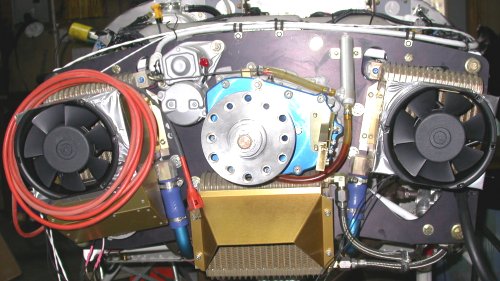 Here, I've duct-taped the muffin fans into the radiator inlet ducts.
This should help keep temperatures under control when running the engine.
Here, I've duct-taped the muffin fans into the radiator inlet ducts.
This should help keep temperatures under control when running the engine.
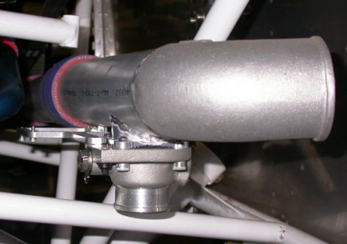 Back when I was first hooking up the supercharger/intercooler plumbing, I'd
considered rotating this tube down like this, so the wastegate wasn't
interfering with the frame diagonal and so the outlet wasn't facing the
firewall. This way, the outlet air would be pointing down, not at the
firewall, and I wouldn't have the interference. To do that, I'd have
had to cut off the ell on this and reweld it so it was pointing up.
But then I ended up making my own wastegate on the other, straight piece of
tubing instead, and blocking off this wastegate port.
Back when I was first hooking up the supercharger/intercooler plumbing, I'd
considered rotating this tube down like this, so the wastegate wasn't
interfering with the frame diagonal and so the outlet wasn't facing the
firewall. This way, the outlet air would be pointing down, not at the
firewall, and I wouldn't have the interference. To do that, I'd have
had to cut off the ell on this and reweld it so it was pointing up.
But then I ended up making my own wastegate on the other, straight piece of
tubing instead, and blocking off this wastegate port.
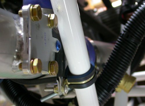 This pic shows how the original wastegate mount placement (in the
foreground) interferes with one of the engine frame diagonals. Routing
a cable here, with the engine frame diagonal right in the way, will be
problematic. It'll be much better in the middle and pointed down
toward the cowl air outlet, as you can see the current brass ball valve
wastegate (in the background) is doing now.
This pic shows how the original wastegate mount placement (in the
foreground) interferes with one of the engine frame diagonals. Routing
a cable here, with the engine frame diagonal right in the way, will be
problematic. It'll be much better in the middle and pointed down
toward the cowl air outlet, as you can see the current brass ball valve
wastegate (in the background) is doing now.
March 14 - Got an email from John Moody, who's building an RV (8-?) with Eggenfellner STi engine in Australia. He pointed out that the Moroso coolant recovery tank has an available lower mount bracket, which would be needed to to properly mount this tank. He says it's Jegs p/n 710-63401. I went back to the page where I bought this on the Summit Racing site, and found the bracket listed under "suggested parts" as a Moroso part number MOR-63401. They also had an installation PDF for the overflow tank. John also thought perhaps my recovery tank was mounted too low, compared to the coolant tank. I'll have to check with Moroso on that. The installation PDF (which I'd gotten a hard copy of with the tank) just says this: Mount the Tank as vertical as possible and make sure the top of the Tank is below the level of the radiator cap. I later called Moroso and asked them the question. They said as long as the recovery tank is below the coolant tank, it will be OK; there isn't a maximum vertical distance. Thanks for the tips, anyway, John! While I guess I'll leave my overflow tank as is for now, it probably is a good idea to minimize the vertical distance between the 2 tanks. Going forward, I'll be monitoring the tanks carefully, to make sure there is no problem with the vertical separation I have.
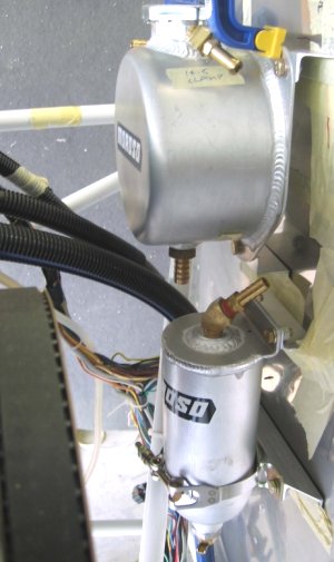 Here is a picture of John Moody's Moroso tanks install. He seems to be
making good use of U-channel for his mountings.
Here is a picture of John Moody's Moroso tanks install. He seems to be
making good use of U-channel for his mountings.
March 15 - There has been quite a discussion on the VAF forum about questionable AN fittings sold by Aircraft Spruce. I checked my stock, and I have about half with an "AN" or "MS" stamp, and the rest are the darker blue, unstamped ones described in the thread. ACS hasn't been exactly forthcoming on the issue, in the opinion of some on the list. I'll contact ACS about the parts I have, and see what they say. 0.25 hr
March 19 - I've been exchanging some emails with Gary Newsted, to get the parts I need to redo my wastegate. In the meantime, I've been working on electrical stuff.
March 21 - received the Gems low fuel pressure sensor I ordered a couple weeks ago. I guess I'm ready to redo the fuel manifold for the third time. Hopefully, version 3.0 will leave me satisfied.
March 22 - Jan got me this info I was seeking: the Bosch pressure relief valve is supposed to open the valve at 12-14 psi and he says about 1/4 throttle (15") of vacuum will cause the vacuum portion of the valve to open it. So, the 0-30 psi fuel pressure sender I ordered from GRT should be perfect for monitoring/alarming SC pressure.
March 23 - remove old (ver 2) fuel pressure distribution manifold. Install version 3. 2.5 hr
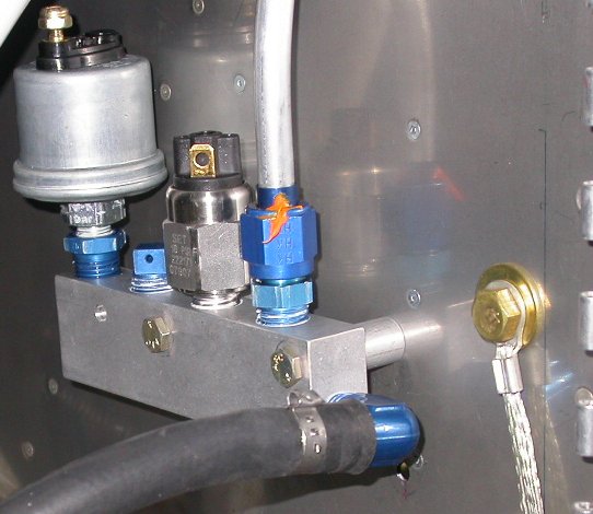 Here is my fuel pressure distribution block, version 3. It has the
VDO pressure sender, the new Gems switch, aluminum tubing outlet, hose inlet from Andair
firewall filter. And they are all mounted with the inlet down, so they
can't trap air, water, crud, etc. The manifold came from ACS with a
mount hole in each end. I drilled a third mount hole in the middle, so
it would better match up with the backing plate I made on the back side of
the firewall. In order to get the VDO sender (p/n 29/4) away from the
firewall, I reused the 2 aluminum spacers I'd made for the Adel clamps in
version 2 of this. Also, this is now full metal-to-metal
contact, so this also solves my problem of grounding the pressure sender.
Ready to wire the sender and the switch now.
Here is my fuel pressure distribution block, version 3. It has the
VDO pressure sender, the new Gems switch, aluminum tubing outlet, hose inlet from Andair
firewall filter. And they are all mounted with the inlet down, so they
can't trap air, water, crud, etc. The manifold came from ACS with a
mount hole in each end. I drilled a third mount hole in the middle, so
it would better match up with the backing plate I made on the back side of
the firewall. In order to get the VDO sender (p/n 29/4) away from the
firewall, I reused the 2 aluminum spacers I'd made for the Adel clamps in
version 2 of this. Also, this is now full metal-to-metal
contact, so this also solves my problem of grounding the pressure sender.
Ready to wire the sender and the switch now.
March 27 - I should have done this the first time; I had used an electrically-conductive grease called NOALOX on the pressure sender threads when I installed it. As my friend Carsten pointed out, I should have also done something to ensure that oxidation between the aluminum spacers and the firewall didn't affect my pressure sensor ground. So, I removed the 2 spacers, coated the ends of both with NOALOX, reinstalled the spacers, and retorqued the two AN3 bolts. 0.25 hr
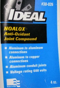 This is
NOALOX, made specifically for ensuring continuity for aluminum connections,
available at any electric supply place. I had used this on the fuel
pressure sender threads, and I also used it on the ends of the aluminum
spacers between the fuel pressure manifold and the firewall.
This is
NOALOX, made specifically for ensuring continuity for aluminum connections,
available at any electric supply place. I had used this on the fuel
pressure sender threads, and I also used it on the ends of the aluminum
spacers between the fuel pressure manifold and the firewall.
March 30 - received wastegate parts from Eggenfellner.
March 31 - lay out for wastegate, trim wastegate. 1.75 hr
Go to APRIL, 2007 engine page
BACK TO MY RV BUILDER'S HOME
BACK TO BRIAN'S HOME