May 1 - TIG welded the LT rad
coolant line I made up, and installed it. I had to bend the header
pipe brace some to clear the hose. New routing is great - no
longer goes under oil filter, as it came from Eggenfellner, so no
interference with oil changes. Added Adel clamps to secure LT radiator
coolant line. Reinstalled Evans NPG+ waterless coolant.
I'd planned to ditch the Evans, but I will continue to try it for now.
It has a much higher boiling point than water, but it also isn't nearly as
efficient at cooling as water. We'll see how it all works with the new
radiators. 2.0 hr
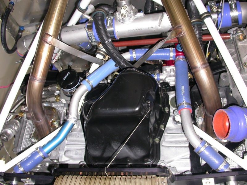
Here is a large detailed pic of the underside of the engine. Bottom of
pic is fwd. The very bottom corners of the pic show the lower radiator
hose fittings. On the lower RT, it shows the 45 I used to
connect the RT rad. For the LT rad, you can see the custom pipe I
welded together from a 45 and a piece of Eggenfellner's tubing to go around
the oil pan. The LT rad line also uses another of the 45s I bought,
partially visible just behind the heater hose (covered with black split
corrugated tubing). The planning & fabrication for the LT coolant line
routing took a lot of dicking around and trying different things to get it
just right. The old line ran right under the center of the oil filter,
and probably would have had to be removed to get the oil filter off.
The heater hose goes under the supercharger air duct. Top of pic is
wastegate and supercharger air ducting to intercooler. On the lower RT,
you can see where the supercharger air inlet goes between engine tubes and
below RT radiator coolant line. The K&N air filter will get plumbed
into that, as soon as it arrives. Scratch marks (I filed them
smooth) on LT header pipe brace show where I had to bend the brace a bit to
make sure it didn't touch the LT coolant hose. I later added an Adel
clamp to the welded tubing in the middle of the LT hose line, to support the
line from flexing. The brown rod is the supercharger belt
tension rod I made back in January with
LT-hand threads on one end, so it can be properly adjusted. RT edge of
pic is bottom of supercharger. Lower LT of pic shows bottom of oil
cooler thermostat and LT header EGT probe. All the header pipe nuts
are safety-wired, as is the oil drain plug. I'll probably have to
safety the drain plug to something else when it comes time to install the
air filter. Pretty busy place under the engine! Finally got it
all so everything manages to avoid hitting anything else.
This show the supercharger inlet air adapter installed. You can also
see the RT radiator lower coolant line installed.
May 2 - resume work on throttle
and wastegate cables. Install clevis tie rods, wire grips, and Bowden
cable clamps onto throttle quadrant. I've found from removing
previously installed wire grips that the tapered part that grips the wire
will twist inside the housing nut when they are tightened, making them,
IMHO, a single-use item. The Bowden cable clamps won't go on over the
Bowden cables. Apparently, the lined cables have a slightly larger
outside diameter than the unlined 7/32" cables. Will need to find or
get probably a "B" drill or reamer for that.
2.0 hr
May 4 - received my K&N air filter
order, placed MSC order in the evening for Bowden cable clamps reamers and a
few other things. The K&N filter looks like it will fit well.
May 5 - received my
MSC
order. MSC is amazing. They always get me my stuff
the next day, which is amazing in itself, but this order wasn't placed until
after 6 PM, so the fact that I still got it the next day shows how super
their customer service is.
May 7 - fitting K&N air filter to
supercharger air inlet & making 2.5" ducting between the two. Cut a
vee-notch out of 0.049" wall 2.5" tubing to change filter angle a bit.
Filed notch a LONG time to get it where I wanted it and with nil gap.
2.0 hr
May 8 - prep & tack MIG weld 2.5"
inlet air duct tubing. 0.5 hr
The
K&N RU-1830 air filter comes with a 10 degree inlet angle. I
needed more angle to make the filter horizontal as the duct comes down from the
supercharger. After cutting out a vee with the bandsaw, I spent a lot
of time filing the edges of the vee so it would come together as tightly as
this. It's now tack welded in place at the bottom with MIG. I'll
finish it at home with the TIG. Using the MIG, especially on thin wall
stuff, is like trying to hit something (and nothing else) with a machine
gun; the TIG is a lot more finesse; like a sniper rifle, using the gun
analogy.
I'm beginning to suspect that, in addition to the other
quality problems mentioned earlier about the Mac's radiators (see
Apr 8,
Apr 17, and Apr 22), I think I may
have a leak in my RT radiator. I may have spilled some when I filled
it and vented the tops of the radiators, but I doubt it. Some
dripping keeps showing up under the engine.
May 9 - TIG welded air inlet
tubing 0.5 hr
May 10 - back to the hangar.
Sure enough, my RT radiator is definitely leaking. Further
checking determined that there are TWO leaks, both at poor welds by Mac's
Radiator. Worked on installing air filter and back to more work on
throttle and wastegate control cables. Drained RT radiator - the bungs
in the lower (outer) corners are quite handy for that.
4.0 hr
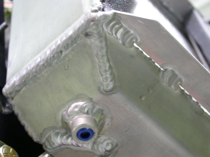
Here are
the 2 leaks in my RT radiator. When I left the hangar a couple
days ago, I thought I had a leak, so I wiped everything up very carefully.
Now, this renewed leak confirms it. The source of the one on the LT is
obvious (the black pinhole directly above the drop of coolant)and should be
easy to fix in place . The one on the RT is a bit more mysterious and
the tank weld is covered up by the flange plate that is tack welded over the
tank welds. &^%$#@ Mac's Radiator and their crappy, sloppy work!
Closeup
of the bottom of the leak on RT in above pic.
Top
pic of same section of weld, from the top. You can see the wet
section.
Here's the same section, after wiping dry. I can't see exactly where
the leak is coming from yet, but I'm fairly sure it's somewhere between
these lines. Mighty poor welding. Don't they test these things
before shipping??? Obviously not. The leak is probably in the
poor edges (black crystal-looking part) of the weld on both sides of the RT
line. The radiator tilts a bit to the LT, so a leak at the RT line
would make it look wet down to the LT line. For past welding needs, I haven't felt confident enough to do my
own welding on plane parts, but given the quantity and quality of TIG
welding I've been doing lately, I feel fairly confident in rewelding this
myself.
May 11 - Decided that I will fix
the radiator myself, but not in place. Removed RT radiator.
Found at least one more leak on the engine side of the radiator after
removing it. More work on throttle/wastegate cables layout.
Installed inlet air duct and K&N air filter.
2.0 hr
This
obvious pinhole on the engine side of the radiator had a drop of coolant
next to it, so I assume this is yet another leak.
Within
a few inches of the above pinhole is this big one in the center of the pic,
as well as the smaller one in the pic lower RT corner.
and
here's yet another one in the same area. There are pinholes all over
these welds.
May 12 - TIG welded all the known leaks and about
a dozen pinholes altogether. The process didn't go real smooth, but
was OK in the end. The new distributed gas lens I got yesterday
helped. It let me put the electrode out further to get into some of
the tighter spots. Fortunately, all known leaks were on the
outer welds. If any had been on the inside, like behind the side
plates, the whole radiator would have had to be redone.
1.5 hr
May 13 - received the Stant
cooling system pressure tester I ordered from Amazon on Monday. After
I reinstall the RT radiator, I'll use it to pressure test the system before
reinstalling the coolant.
May 14 - Reinstalled RT radiator
and pressure-tested it at 7 pounds for a couple hours - no leaks at all.
All seemed good, so I bolted it on, refilled all the coolant, and
pressure-tested it all one more time. Resumed working on throttle &
wastegate cables. Used new Greenlee punch to punch a hole in firewall
for a second cable. It didn't work very well - it made a ragged hole
because the pilot hole was nearly as big as the punch hole and because the
stainless steel is so tough. It also made the hole a bit too big; I
should have just used a hole saw, as I've done before. Drilled metal
grommet eyeball out to #1, then reamed to 15/64". Spent a bunch of time on a
very careful layout for the cables; routing, lengths, curve radii, angles,
supports, etc. Diddled around a lot with wastegate cable
routing, but finally got the housing installed.
6.0 hr
This shows the Stant cooling system pressure tester in operation.
It worked great, and seemed to be well made with good materials. Cost
about $70 from Amazon. Some of these cost over $500. A lot
of what you are paying for in the more expensive kits is all the adapters.
If you can use a standard "A" cap, like here, then a simple one like this
that doesn't come with a lot of adapters is what you need.
May 15 - Went out flying in the
morning in the Challenger with my friend George Ward. I got a weather
brief, and they said winds max 8, but it was really too windy; gusting up to
20. The hour-long flight was pretty bouncy, and coming in on final was
quite wild. OK landing, though. After lunch, George was a big
help in completing the installation and adjustment of both throttle and
wastegate cables. Now, I just need to reconnect the batteries and DC
control wiring, and the engine will be ready to start again.
3.0 hr
After getting the routing for the cable housings arranged and cut to length,
I put the inner wires in, cut them to length, and connected them to the quadrant.
Here is the throttle cable all installed and adjusted.
This pic from under the engine shows the air filter installed onto the
angled 2.5" duct I welded. In the background, at the lower LT edge of
the pic, you can see the two "one-hole" metal firewall grommets I used to
get the throttle and wastegate cables through the firewall. Both
throttle and wastegate cables are all installed and adjusted now. The
wastegate cable took a lot of planning to minimize the radius of the bend
and to clear everything in its path.
May 18 - I found out that one of
the few remaining Eggenfellner-supplied components of this FWF horror story
is also designed wrong. An alternator is supposed to spin at max
10,000 rpm. The pulley ratios Eggenfellner chose will run our
alternator at 13,500 rpm at 2700 prop rpm! At anything over 4,000
engine rpm, the alternator is being overspeeded. This is the same
problem as with the wrong pulley/speed selections Eggenfellner made with
overspeeding the supercharger (see June, 2007),
necessitating that I buy a new custom supercharger pulley (see
July, 2008). I found out alternators reach their maximum output
typically around 6,000 rpm, and that increasing the speed beyond this does
not increase the output, yet it increases the horsepower consumption of the
cooling fans. I'm told alternators perform best between 2,400 RPM and
6,000 alternator rpm, with the greatest efficiency at 2,400 alternator rpm.
I may or may not swap out the alternator pulley. At least a
couple of the few remaining STi owners are swapping out the entire
alternator and its fragile Eggenfellner mounting system for a more powerful
one and a more robust mounting.
May 21 - It still looks and
smells like I have some coolant seepage. Funny -it never leaked
before. It seems it may be coming from around the main drain plug on
the red anodized coolant distribution block. I modified a 9/16" Allen
wrench to get into the short space between the plug and the supercharger
belt adjustment rod right under the plug. I managed to get the plug a
bit tighter - we'll see what things look like tomorrow morning. Worked
on fine-tuning throttle cable adjustment. I wanted to confirm for sure
that the throttle opened all the way, so I removed the intake air temp
sensor probe housing and used a penlight and mirror to confirm the throttle
butterfly goes fully flat when the quadrant lever is fully forward.
Reinstalled & sealed intake air temp sensor mount. Worked some on
securing more engine wiring harness. 2.5 hr
May 22 - I put a box-end wrench
on the end of the 9/16" Allen wrench and got the main coolant drain plug a
bit tighter - maybe a total of 25 degrees or so. I don't see any more
sign of seepage. Also tightened up inlet air temp probe mount plate
after the sealant had cured. 0.5 hr
May 23 - Installed & reconnected
DC control panel and batteries. All looked OK, but when I turned on
the ECU switch, the coils fuse blew immediately. There's some
confusion on my part now as to how the coils were supposed to be wired -
obviously NOT as I wired them. Emailed Ross, John, Randy to ask for
clarification. 2.5 hr
May 26 - Randy, John, and Ross
all confirmed that how I thought coils should be wired is the correct way,
so I must have made a mistake somehow. Will check it out later in week
when I go to hangar. At this point, I can't imagine how I could have
miswired it, as I'm very careful in my wiring, but obviously I've done
something wrong.
This how the STi coils are supposed to be wired, and how I thought I did it.
I must have cross-wired something.
May 27 - finally got around to
calling Mac's Radiator about the radiator quality problems. Talked to Curtis MacDonald, the owner. He asked me to forward
him the emails Randy and I had sent Sam, along with the pictures of the quality problems.
He said
he'd look into it and get back to us. JULY, 2009 FOLLOWUP:
We never heard from Curtis again. Obviously, his company's
poor product quality and poor customer service begin with him.
Randy and I strongly recommend against doing business with Mac's Radiator.
May 28 - opened up wiring harness
and confirmed I wired it as per above drawing. The coils circuit
itself isn't shorting out, but the coils circuit fuse blows when I turn on
the ECU. To me, that seems like the ECU is constantly triggering the
coil. Emailed Ross to get his help on it. Ross suggested
it could be the ECU ground. Sure enough - I had installed the ECU
ground (a long time ago) in a separate location, as per instructions, but when I was tying up
the harness recently, I disconnected the ECU ground to get better access to the
harness to wrap silicone tape around it where it went through the firewall.
After doing all the harness securing, I'd forgotten to reconnect the ground.
After finishing the silicone tape wrap and reconnecting the ground, the
coils are no longer being energized when I engage the ECU switch.
Agreed to buy a MT prop brush mount bracket from another Egg customer. Ran
engine briefly to prove it will run. Idle speed needs adjusting.
ET & AT (engine temp & air temp) values are way off from EIS values.
Not getting any EIS tach reading; things to fix.
2.5 hr
May 29 - Running engine more &
checking things out. Hooked up timing light & set SDS timing initial
value (magnet position = 90). It runs a bit rough & seems to prefer
being set to 10-15% leaner. Will get into tuning later.
Set idle speed stop on throttle body. Ross helped with ET/AT values by
telling me what brand sensors to configure in the ECU. Getting better
readings now. Enabled EIS page 5 (EGT). John Moody sent me
advice on modifying the EIS PC board so it will see the SDS tach signal.
Still seems to idle better at 10-15% leaner.
2.0 hr
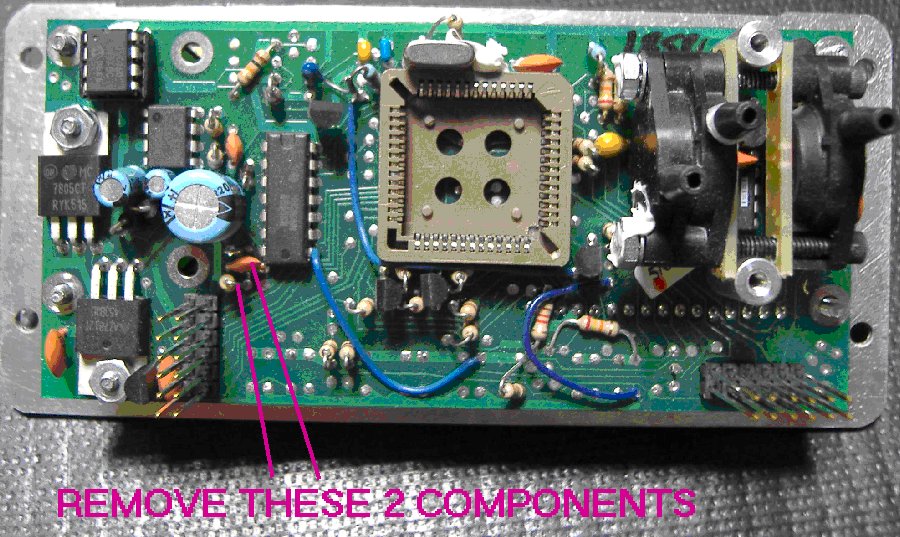
Remove these 2 components (resistor and capacitor) to make the EIS work with
the SDS or other electronic ignitions, such as Lasar. Click HERE to see
removal instructions and a drawing of the 2 components to remove. Click HERE to see
GRT's
photo of the same thing.
May 30 - more engine runs &
tweaking the instrumentation. It seems to not have a cold high idle,
like in a car. Not sure now if that's how it is with SDS or if the SDS
configuration needs some tweaking. Doing it manually with the throttle
lever for now. Set SDS oxy sensor brand parameter & now getting
air/fuel mixture readings ok. Used that to confirm I need 15%
leaner at 1250 rpm and 10% leaner at 1500 rpm. This SDS is pretty
slick. 1.0 hr
 Here is a large detailed pic of the underside of the engine. Bottom of
pic is fwd. The very bottom corners of the pic show the lower radiator
hose fittings. On the lower RT, it shows the 45 I used to
connect the RT rad. For the LT rad, you can see the custom pipe I
welded together from a 45 and a piece of Eggenfellner's tubing to go around
the oil pan. The LT rad line also uses another of the 45s I bought,
partially visible just behind the heater hose (covered with black split
corrugated tubing). The planning & fabrication for the LT coolant line
routing took a lot of dicking around and trying different things to get it
just right. The old line ran right under the center of the oil filter,
and probably would have had to be removed to get the oil filter off.
The heater hose goes under the supercharger air duct. Top of pic is
wastegate and supercharger air ducting to intercooler. On the lower RT,
you can see where the supercharger air inlet goes between engine tubes and
below RT radiator coolant line. The K&N air filter will get plumbed
into that, as soon as it arrives. Scratch marks (I filed them
smooth) on LT header pipe brace show where I had to bend the brace a bit to
make sure it didn't touch the LT coolant hose. I later added an Adel
clamp to the welded tubing in the middle of the LT hose line, to support the
line from flexing. The brown rod is the supercharger belt
tension rod I made back in January with
LT-hand threads on one end, so it can be properly adjusted. RT edge of
pic is bottom of supercharger. Lower LT of pic shows bottom of oil
cooler thermostat and LT header EGT probe. All the header pipe nuts
are safety-wired, as is the oil drain plug. I'll probably have to
safety the drain plug to something else when it comes time to install the
air filter. Pretty busy place under the engine! Finally got it
all so everything manages to avoid hitting anything else.
Here is a large detailed pic of the underside of the engine. Bottom of
pic is fwd. The very bottom corners of the pic show the lower radiator
hose fittings. On the lower RT, it shows the 45 I used to
connect the RT rad. For the LT rad, you can see the custom pipe I
welded together from a 45 and a piece of Eggenfellner's tubing to go around
the oil pan. The LT rad line also uses another of the 45s I bought,
partially visible just behind the heater hose (covered with black split
corrugated tubing). The planning & fabrication for the LT coolant line
routing took a lot of dicking around and trying different things to get it
just right. The old line ran right under the center of the oil filter,
and probably would have had to be removed to get the oil filter off.
The heater hose goes under the supercharger air duct. Top of pic is
wastegate and supercharger air ducting to intercooler. On the lower RT,
you can see where the supercharger air inlet goes between engine tubes and
below RT radiator coolant line. The K&N air filter will get plumbed
into that, as soon as it arrives. Scratch marks (I filed them
smooth) on LT header pipe brace show where I had to bend the brace a bit to
make sure it didn't touch the LT coolant hose. I later added an Adel
clamp to the welded tubing in the middle of the LT hose line, to support the
line from flexing. The brown rod is the supercharger belt
tension rod I made back in January with
LT-hand threads on one end, so it can be properly adjusted. RT edge of
pic is bottom of supercharger. Lower LT of pic shows bottom of oil
cooler thermostat and LT header EGT probe. All the header pipe nuts
are safety-wired, as is the oil drain plug. I'll probably have to
safety the drain plug to something else when it comes time to install the
air filter. Pretty busy place under the engine! Finally got it
all so everything manages to avoid hitting anything else.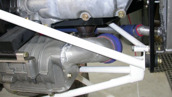 This show the supercharger inlet air adapter installed. You can also
see the RT radiator lower coolant line installed.
This show the supercharger inlet air adapter installed. You can also
see the RT radiator lower coolant line installed.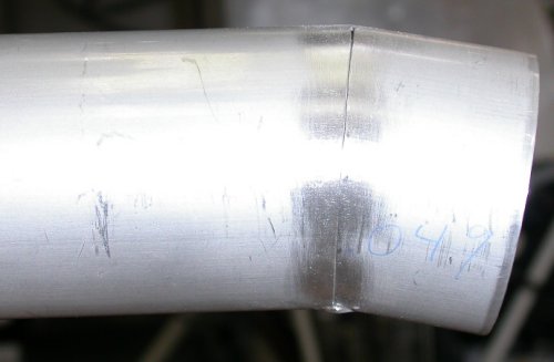 The
The
 Here are
the 2 leaks in my RT radiator. When I left the hangar a couple
days ago, I thought I had a leak, so I wiped everything up very carefully.
Now, this renewed leak confirms it. The source of the one on the LT is
obvious (the black pinhole directly above the drop of coolant)and should be
easy to fix in place . The one on the RT is a bit more mysterious and
the tank weld is covered up by the flange plate that is tack welded over the
tank welds. &^%$#@ Mac's Radiator and their crappy, sloppy work!
Here are
the 2 leaks in my RT radiator. When I left the hangar a couple
days ago, I thought I had a leak, so I wiped everything up very carefully.
Now, this renewed leak confirms it. The source of the one on the LT is
obvious (the black pinhole directly above the drop of coolant)and should be
easy to fix in place . The one on the RT is a bit more mysterious and
the tank weld is covered up by the flange plate that is tack welded over the
tank welds. &^%$#@ Mac's Radiator and their crappy, sloppy work!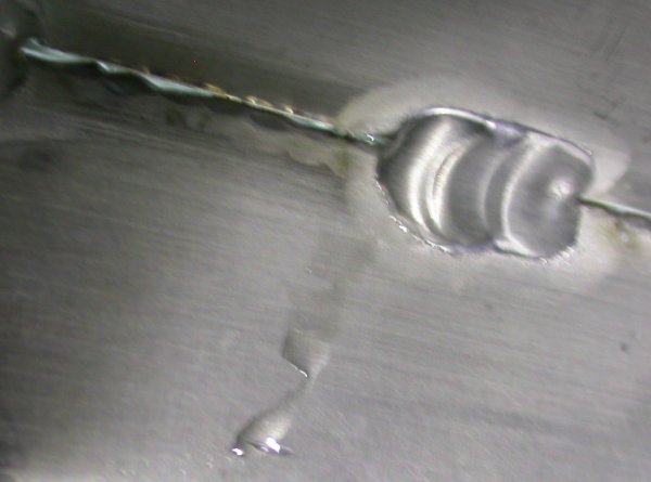 Closeup
of the bottom of the leak on RT in above pic.
Closeup
of the bottom of the leak on RT in above pic.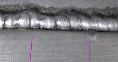 Top
pic of same section of weld, from the top. You can see the wet
section.
Top
pic of same section of weld, from the top. You can see the wet
section.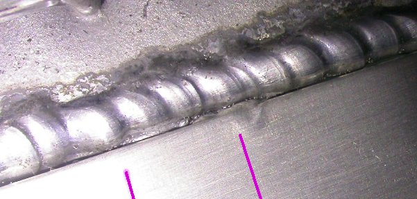 Here's the same section, after wiping dry. I can't see exactly where
the leak is coming from yet, but I'm fairly sure it's somewhere between
these lines. Mighty poor welding. Don't they test these things
before shipping??? Obviously not. The leak is probably in the
poor edges (black crystal-looking part) of the weld on both sides of the RT
line. The radiator tilts a bit to the LT, so a leak at the RT line
would make it look wet down to the LT line. For past welding needs, I haven't felt confident enough to do my
own welding on plane parts, but given the quantity and quality of TIG
welding I've been doing lately, I feel fairly confident in rewelding this
myself.
Here's the same section, after wiping dry. I can't see exactly where
the leak is coming from yet, but I'm fairly sure it's somewhere between
these lines. Mighty poor welding. Don't they test these things
before shipping??? Obviously not. The leak is probably in the
poor edges (black crystal-looking part) of the weld on both sides of the RT
line. The radiator tilts a bit to the LT, so a leak at the RT line
would make it look wet down to the LT line. For past welding needs, I haven't felt confident enough to do my
own welding on plane parts, but given the quantity and quality of TIG
welding I've been doing lately, I feel fairly confident in rewelding this
myself. 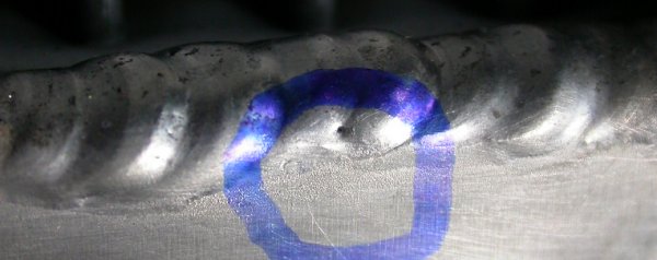 This
obvious pinhole on the engine side of the radiator had a drop of coolant
next to it, so I assume this is yet another leak.
This
obvious pinhole on the engine side of the radiator had a drop of coolant
next to it, so I assume this is yet another leak.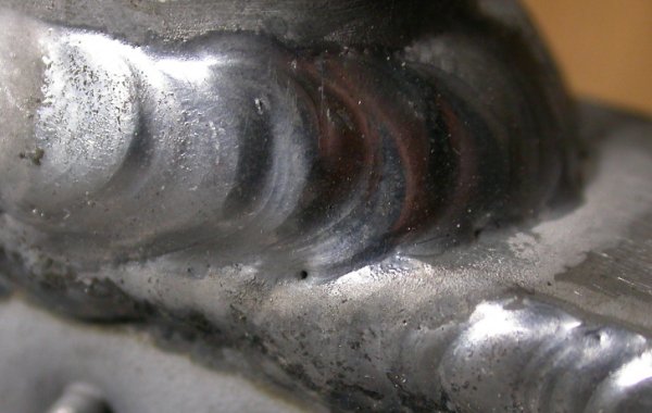 Within
a few inches of the above pinhole is this big one in the center of the pic,
as well as the smaller one in the pic lower RT corner.
Within
a few inches of the above pinhole is this big one in the center of the pic,
as well as the smaller one in the pic lower RT corner.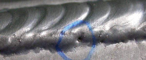 and
here's yet another one in the same area. There are pinholes all over
these welds.
and
here's yet another one in the same area. There are pinholes all over
these welds.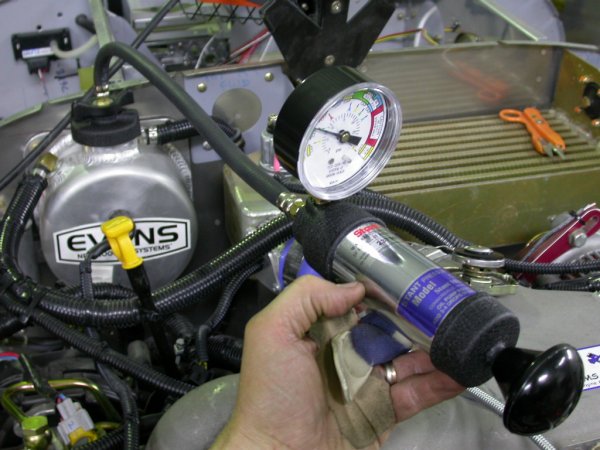 This shows the Stant cooling system pressure tester in operation.
It worked great, and seemed to be well made with good materials. Cost
about $70 from Amazon. Some of these cost over $500. A lot
of what you are paying for in the more expensive kits is all the adapters.
If you can use a standard "A" cap, like here, then a simple one like this
that doesn't come with a lot of adapters is what you need.
This shows the Stant cooling system pressure tester in operation.
It worked great, and seemed to be well made with good materials. Cost
about $70 from Amazon. Some of these cost over $500. A lot
of what you are paying for in the more expensive kits is all the adapters.
If you can use a standard "A" cap, like here, then a simple one like this
that doesn't come with a lot of adapters is what you need.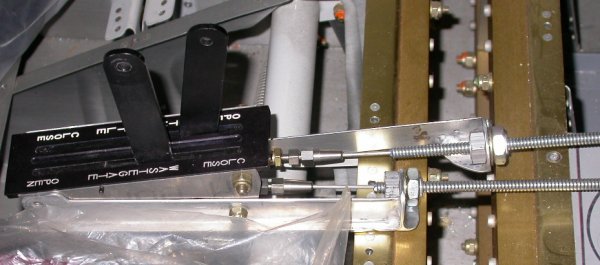 After getting the routing for the cable housings arranged and cut to length,
I put the inner wires in, cut them to length, and connected them to the quadrant.
After getting the routing for the cable housings arranged and cut to length,
I put the inner wires in, cut them to length, and connected them to the quadrant.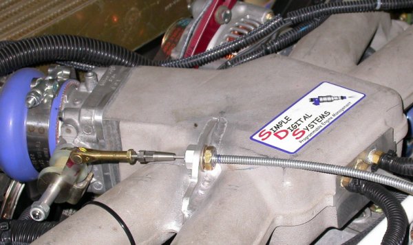 Here is the throttle cable all installed and adjusted.
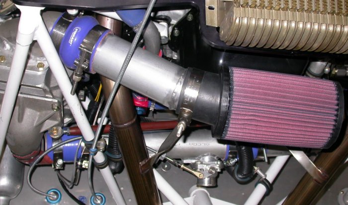 This pic from under the engine shows the air filter installed onto the
angled 2.5" duct I welded. In the background, at the lower LT edge of
the pic, you can see the two "one-hole" metal firewall grommets I used to
get the throttle and wastegate cables through the firewall. Both
throttle and wastegate cables are all installed and adjusted now. The
wastegate cable took a lot of planning to minimize the radius of the bend
and to clear everything in its path.
This pic from under the engine shows the air filter installed onto the
angled 2.5" duct I welded. In the background, at the lower LT edge of
the pic, you can see the two "one-hole" metal firewall grommets I used to
get the throttle and wastegate cables through the firewall. Both
throttle and wastegate cables are all installed and adjusted now. The
wastegate cable took a lot of planning to minimize the radius of the bend
and to clear everything in its path.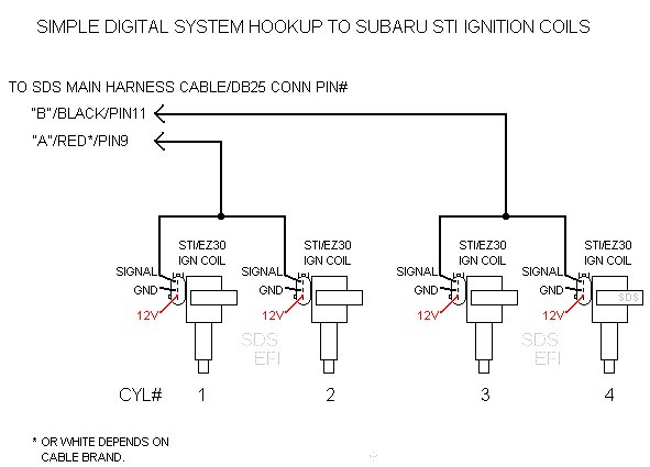 This how the STi coils are supposed to be wired, and how I thought I did it.
I must have cross-wired something.
This how the STi coils are supposed to be wired, and how I thought I did it.
I must have cross-wired something. 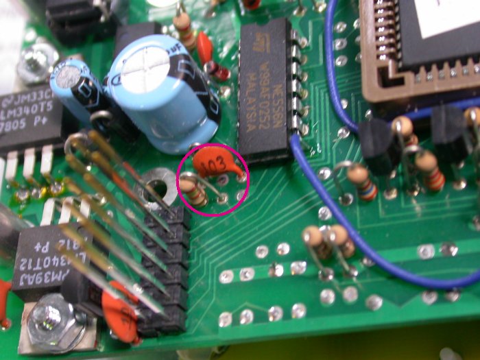 Remove these 2 components (resistor and capacitor) to make the EIS work with
the SDS or other electronic ignitions, such as Lasar. Click
Remove these 2 components (resistor and capacitor) to make the EIS work with
the SDS or other electronic ignitions, such as Lasar. Click 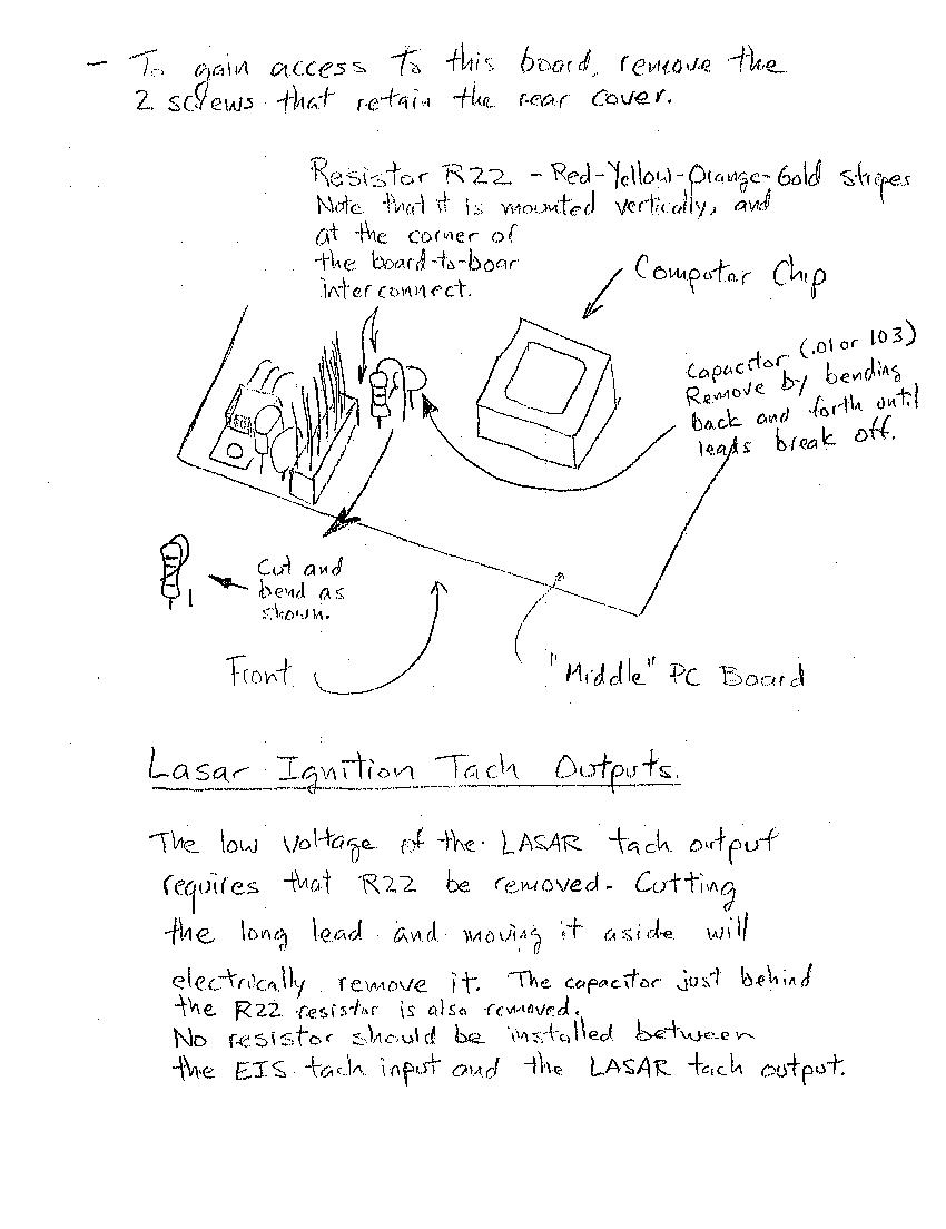